Introduction
As a reminder of what we're trying to do, here is a visible-light image of a vinca plant growing through a retaining wall, taken with the same camera using a single fused silica lens element and with our final design.
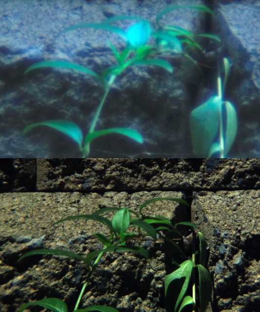
Fig. 1. Top: Image of a retaining wall taken with single fused silica element. Bottom: Image taken with CaF2/silica triplet designed here (UV-IR block filter; cropped and resized)
The top image has all the characteristics of spherical aberration: massive fuzziness, low contrast, and halo around all the bright areas. To eliminate this, we use a CaF2/silica triplet to reduce the aberrations, and a fourth element to reduce the focal length. Although we didn't get as much reduction in focal length as hoped, the image (bottom) is much sharper and has much better contrast.
Camera
It is essential to use a modified camera to capture wavelengths below 390 or above 650 nanometers. For this project, I used a modified Nikon D90 DSLR. This camera is fairly easy to modify for infrared and ultraviolet. Unlike later models, it also has an AC adapter plug on the side. When running on AC power, the LCD display remains on continuously, which is very convenient when performing tests and alignment. This makes the D90 a better experimenter's camera than some of the later models.
Mechanics
So now we consider how to handle the mechanical aspect. Since I am by no stretch of the imagination a good machinist, as well as being incredibly lazy, we will just use a very simple mechanical design. Calculations showed that since the sensor is 46.5 mm from the mount, the overall length of the lens would have to be at least 88.4 mm + the thickness of the triplet, which is 25.4 mm. Add another 10 for the iris diaphragm, for a total of 123.8. That's how long our zoom lens has to be.
Here are the design parameters:
- Fixed external size—no telescoping cylinders moving in and out, which would require cutting helical threads on a lathe.
- Lenses should not rotate when focusing—this would make alignment and centering more difficult.
- Nothing will be built into the lens housing—this allows us to take it apart easily by removing a couple of screws. The advantage of this is easy modification, in case we decide to change it.
- The focusing element will travel back through the lens mount as far as possible, to maximize the zoom range.
A rack-and-pinion system uses a fixed rack (essentially a linear gear) and a round gear (pinion) that moves along with the platform. To use a rack and pinion, we either have to cut slots along the length of the lens and mount the gears inside, or mount the gears outside and use a bellows, like an old-fashioned camera, or telescoping plastic cylinders. That is what we will do.
Before starting, I made a crude mock-up to find out if the computer simulations were telling me the truth. These tests showed that it was essential to keep the optical path completely separate from the mechanical parts, and for the lens elements to occupy the full diameter of the tube so that light can't go around the outside of any of the optical elements. Otherwise, you will get reflections and stray light that is hard to get rid of.
The mock-up also showed where to put the aperture stop. Every optics book that I've seen says that the position of the stop is critical, but none of them tell you where to actually put it. It turns out that if it's too close to a focus point, you will get vignetting. So the best place is right behind the triplet:
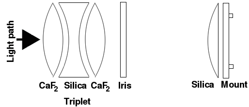
Fig. 3. Light path
I finally realized I had bitten off more than I could chew as far as my machining skills were concerned, so I decided to build the lens mechanism around a Thorlabs SM1NR1 zoom housing, which provides fairly precise alignment and non-rotating zooming. Unfortunately, after this page was written, these little babies just zoomed up in price.
The disadvantage of the SM1NR1 is that there's no good place to put an aperture stop. If you attach it to the back, you get vignetting because it's too close to the focusing lens. Putting it in front of the triplet also causes vignetting. I finally decided to use a fixed stop (a piece of 1-inch diameter black plastic with a 0.5-inch diameter hole) inside the lens tube containing the triplets (Fig. 5).
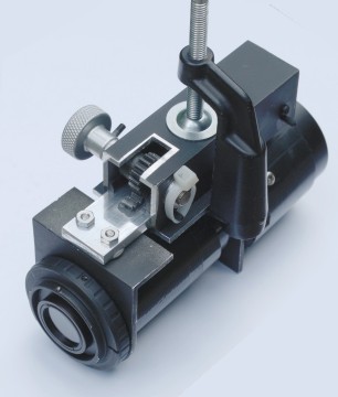
Fig. 4. The lens consists of three pieces: the lens mount/rack gear, the square tube containing the round pinion gear, and the zoom housing, which is mounted on a 1/8" thick aluminum angle (see Fig. 8) which is clamped to the square tube. (bottom view)
To turn this into a zoom lens, we still need a z-axis mount to focus it. I used a rack-and-pinion gear mounted in a one-inch (i.d.) square aluminum tube as shown at right. The gear (McMaster-Carr) was press-fitted onto a stainless steel rod. One end of the rod has an aluminum knob attached. I milled a rectangular space in a chunk of ¼-inch thick × 1 inch wide aluminum (not easy to do without an actual mill), which was ground to fit tightly inside the square tube, and epoxied the rack in place. Note the clever use of a C-clamp to hold this baby together. A piece of adhesive-backed teflon between the inside of the square tube and the flat surface of the unpainted aluminum flat (to which the rack gear is attached) provides smooth turning. So smooth, in fact, that it was necessary to add a plastic tie-strap to increase friction to prevent the lens from zooming by itself and falling off into the dirt when the lens was pointed down.
Two thin strips of black Delrin (barely visible in the photo) keep the aluminum flat in place inside the tube. All metal parts were either aluminum or stainless steel. We don't want to even think about getting rust on these expensive CaF2 lenses.
Aluminum washers (¼" thick) are glued to the stainless steel rod on the outside of the square tube to prevent it from moving left and right. In retrospect, I should have also sprung for a second knob to make it more symmetrical.
Update I eventually put a second knob on the other side. Using two knobs eliminates the need for gluing anything to the shaft, but the tie strap we used to create friction will no longer work. Putting non-metallic washers on the shaft is a good substitute.
To attach the lens to the camera, I used a Fotodiox Lens Mount Adapter (T2-Nikon), which consists of two concentric rings. I attached the inner ring to an L-shaped piece of 1/8" thick aluminum angle with four 2-56 flat-head stainless steel screws. The outer ring, which attaches to the camera, can be rotated as needed and tightened with three little set screws. This makes it very convenient in case you decide to switch to a different camera—just change the outer ring.
Note in Fig. 4 that the top of the aluminum angle is cut to match the curvature of the lens mount adapter. If this is not done, it will prove to be impossible to attach this thing to a camera.
Mounting the optics
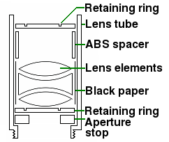
Fig. 5. Installing lenses in a lens tube
It turns out that extreme precision is critical for a Cooke triplet. If the lens elements are a fraction of a millimeter off, you will get bad blurring around the edges. Just placing the lenses inside the lens tube isn't enough. You also need spacers around the outside to ensure a precise fit. To do this, take a 1-inch lens tube (Thorlabs SM1L10), and wrap the inside with a single layer of black paper so the lenses fit tightly in the tube. Insert a precisely-cut ring made from a 10-mm wide piece of 0.02-inch thick black ABS (McMaster-Carr 8586K98), followed by a retaining ring, to hold the lenses in place. All this must be done without scratching or chipping the fragile calcium fluoride or getting dirt between the elements.
From the computer simulation, we also know that the spacing between the elements is critical. I tried different numbers of spacers, and the configuration without spacers seemed to work best. It's not usually recommended to stack lens elements without spacers because of the risk of scratching, and spacers don't hurt the image quality too much, so it's okay to use a spacer if you want. The important thing is to make sure the polished faces aren't touching each other.
The lens tube screws into the front of the zoom housing. The 4th (focusing) lens in the back is mounted inside another 1-inch lens tube that screws into the back. Every part has to be centered precisely on the optical axis, and the lenses have to be precisely perpendicular to it. That's what that fancy C-clamp in Fig. 4 is for. Don't attach the two halves together permanently until you're satisfied they're perfectly aligned.
Making it light-tight
To prevent stray light from getting in, make two telescoping tubes from that 0.02 inch thick black ABS. Blocking stray light is especially important for UV photography. Adhesive-backed black-out paper (McMaster 9019T2) comes in handy for this. I used a ton of this stuff on my spectrograph, but it's also useful here for lining the insides of the ABS tubes. Alternatively, you can wrap microfiber towels around it, holding them in place with duct tape. Don't laugh, it works great.
Attaching filters
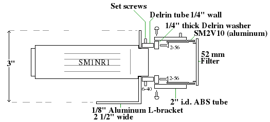
Fig. 5. Attaching filters to zoom housing.
Attach the SM1NR1 zoom housing to another L-shaped piece of aluminum angle (with an appropriately sized hole in the center) by sliding a 1–2 inch long piece of ¼" wall thickness black Delrin tube over the nosepiece and tightening it down with four 6-40 set screws. (I used some more ABS underneath to avoid scratching the nosepiece). To the front of this tube, attach a larger Delrin ring with four screws. Then slide a 2-inch long piece of 2" i.d. ABS from a local hardware store over the outside and fix it into place with stainless steel screws. A Thorlabs SM2V10 tube just happened to fit inside this ABS, so I fixed it in place with another 6-40 set screw.
These tubes are fairly expensive, but they're convenient because they're the perfect thread size, almost, for a 52-mm filter. This means you can attach your existing filters by using step-up or step-down rings. An alternative solution is to attach a step-down ring or an adapter from one of those Cokin P-style filter holders. These may look funny but they give you lots of area to work with. Or use a lathe to cut some threads to the appropriate size.
Alignment
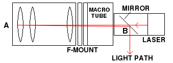
Fig. 6. Alignment. The elements are adjusted so the beam is at the center at points A and B. The ‘mirror’ is a thin piece of ordinary glass. The laser is clearly visible wherever it enters or leaves a transparent surface.
Even though we're not doing real engineering here, we still need to test the final product with the camera mount in place, to make sure everything is centered and parallel to the camera sensor. Tilt and decenter cause blurring, astigmatism, and coma. Professionals would use expensive testing equipment, but a cheap and easy way is to use a macro extension tube attached to a laser collimator of the sort used by amateur astronomers for collimating telescopes. The general idea is to reflect a thin laser beam off the lenses and observe the beam.
