Introduction
 n the visible range, there are lots of outstanding commercial zoom lenses to choose from.
Unfortunately, these lenses pass little or no ultraviolet light below 400 nanometers.
Even fixed-focus lenses are pretty much opaque below 380 nm. For UV photography,
this is just not good enough. There are few if any UV lenses on the market,
and their prices are astronomical—starting at $2000 for a basic fixed-focus
lens.
That is, if you can find them. The only one I could find that is available today is Jenoptik's CoastalOpt 105mm lens, which covers f/4.5 to f/32, and has a fixed focal length of 105 mm. It's a higher optical quality than the one we're building here, but the asking price as of this writing is $4,495. Another great commercial UV lens is the legendary UV-Nikkor 105 mm f/4.5 lens. Alas, it is no longer available.
So it makes sense to build your own. But it turns out that designing good quality lenses for UV photography is much harder than for the visible range. There are several reasons for this, and unless you're willing to spend tons of money on it, the result is rarely as good as we might hope.
Disclaimer
This is a spare-time amateur project. I am not an optical engineer. If you find any errors on this page, please send me a note at the address in the column at right.
Materials
There are several unique challenges to working in the UV. First, the choice of materials is more limited. To correct for chromatic aberration, you need two materials with widely different dispersions. The only UV-transmitting materials in common use are fused silica and calcium fluoride (CaF2), and both of these have low refractive indexes compared to lanthanums and crowns used in the visible. A few lens elements are also available in magnesium fluoride (MgF2), which has an even lower refractive index. Low refractive index means that strong curvature is needed to produce the same optical effect. This in turn causes high spherical aberration. That's one reason why infrared lenses made of silicon and germanium are easy to make in high quality: the RI of germanium at 2 µm is 4.104, so even an almost flat lens bends light by a large amount. By contrast, a lot of curvature is needed for fused silica and CaF2.
Here is a table of refractive indexes for common UV materials, so you can see what I mean.
Refractive index of UV transparent materials| nm | Fused silica | CaF2 | MgF2 |
|---|---|---|---|
| 200 | 1.53836 | 1.49535 | 1.42309 |
| 254 | 1.50533 | 1.46589 | 1.40176 |
| 300 | 1.48779 | 1.45403 | 1.39298 |
| 350 | 1.47689 | 1.44654 | 1.38739 |
| 365 | 1.47454 | 1.44491 | 1.38617 |
| 400 | 1.47012 | 1.44185 | 1.38387 |
A second drawback is the cost. The software costs are the same, but materials costs are much higher than for BK7 and other materials for visible light. In the UV, surface tolerances are also much tighter, because of the shorter wavelength. This is a particular problem for mirrors, but even for refractive lenses it raises the cost, because they have to be polished to a much greater degree of accuracy.
Third, for a commercial design, a manufacturer can afford to have custom lenses made. To reduce costs, we have to use stock lenses, which might not have the exact curvature that the software calls for. What this means is that you cannot expect to achieve the same MTF and aberration levels as for a commercial lens. CaF2 is also very soft, which means extreme care is needed to prevent scratches during assembly.
Simple UV Lens design
At first glance, you might think, as I did, “sure, this is easy. We just buy a little fused silica lens with the right focal length and slap it in.” Unfortunately, a single-element lens gives a pretty bad result, as you can see from the example photograph below (Fig. 1).

Fig. 1. Comparison of single-element quartz lens vs. commercial glass lens for ultraviolet photography. Settings: Left=f/3 fused silica lens, Right=f/2.8 Nikkor 60mm f/2.8D. Both images were taken with a modified D90, 1/20 sec, ISO 1600, using a Baader U filter. The quartz lens was over four times more sensitive than the glass Nikkor lens. Shorter UV wavelengths appear red instead of blue due to peculiarities in the RGB coating on the camera's sensor. Spherical aberration is evident in the quartz lens.
The ray trace analysis in Fig. 2 below explains why. Notice that the spherical aberration is over 15 mm in the midpoint of the lens (x-axis in the graph below). The curves also bend off to the left, which is also bad, as we get farther from the midpoint. Spherical aberration will cause your photos to have a bad halo around the bright areas. In principle, we could save this lens by stopping it way down. This gets the SA pretty close to zero, at least for one wavelength at a time, as shown in Fig. 3 below, but the trade-off is that exposure time increases drastically. For example, when we reduce the aperture from 25 to 4 mm, we lose 97.4% of the light, so we need to expose 39 times longer. This is a disaster in the ultraviolet, where exposure times are already on the order of 1–2 seconds, even in full sunlight. Such a small aperture could also make your images fuzzier due to diffraction.
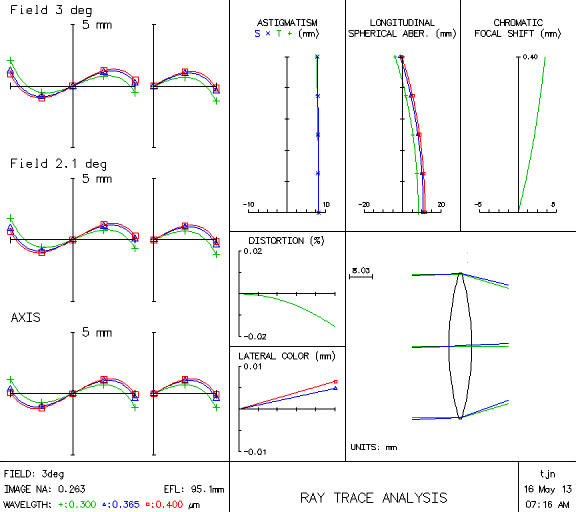
Fig. 2. Ray trace analysis of fused silica single lens (beam radius = 25.4 mm)
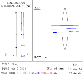
Fig. 3. Ray trace analysis of fused silica single lens stopped down from 25 to 4 mm beam radius
When the third-order spherical aberration (called SA3 for short) is negative, it means the peripheral rays are not bent enough. When it's positive, the peripheral rays are bent too much. We want the SA3 to be as close to zero as possible. Fig. 4 shows how stopping down a lens improves the 3rd order spherical aberration. The effect is dramatic—it can be shown that SA varies with the 4th power of the radius. It also varies inversely with the 3rd power of the focal length. So if you're content with taking pictures of far-away objects and very long exposure times, or if you like lots of halos around your objects, you can stop reading here and start slapping stuff together.
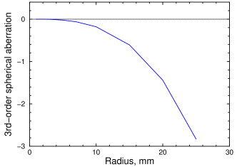
Fig. 4. Third-order spherical aberration vs. aperture for a single double-convex fused silica lens
The other big problem that we often see in the ultraviolet is chromatic focal shift. Some commercial lenses compromise by allowing residual aberrations in the blue, reasoning that the eye is less sensitive to blue, so the customer won't notice. This in turn has created a demand for filters to get rid of blue altogether. Those blue blocker sunglasses that were so popular in the 1990s were based on the same principle. Chromatic focal shift is the x-axis difference between the red, green, and blue curves on the SA plot in Fig. 3. Spherochromatism is similar: it is the difference in SA at different wavelengths. In a single element lens, you would have to re-focus by 3 mm when changing from 300 to 400 nm. This is acceptable when you have a monochromatic source like a laser, but for a general photographic lens it would cause big problems.
CaF2 Triplet UV Zoom Lens Design
Lots of the problems alluded to above could be solved by using an aspheric lens. But aside from the fact that aspheric fused silica lenses are prohibitively expensive, a single aspheric lens will not give you zooming.
While experimenting with a variety of configurations on the computer, I found a great many designs that could minimize SA at a single wavelength. But they all had lots of primary axial chromatic aberration. This means that they're only good for a single λ—if you want to photograph a different wavelength, you would have to re-focus. So our goal is not only to eliminate spherical aberration. We also need to get those three curves (shown as red, green, and blue on the ray trace diagram) as straight and as close to each other as possible. The only design I could find that worked in the UV was a Cooke triplet.
A Cooke triplet is a sandwich of three closely-spaced lens elements: two double convexes around a double concave. The concave one has to be made of a different material with a different RI, so there are only two possible configurations: low-high-low and high-low-high. Calculations showed that only the low-high-low combination would give an acceptable result. This means our sandwich has to be two CaF2 double convex elements surrounding a fused silica double concave element. This is because the dispersion of silica is greater than that of calcium fluoride, as can be seen in the table above.
Another advantage is that the Cooke triplet is considered “prior art,” which means you shouldn't have lawyers chasing after you if you decide to build one. But ambulance-chasers can be a devious bunch, and I make no promises if you try to sell one of these lenses commercially. The lens we're building here is really just for educational purposes. Really.
By itself, this design worked well on the computer, but it had a focal length of 143 mm, which is practically in the telephoto range. Most UV photos are close-ups, which means we need to shorten this. We can't change the curvature or spacing between the elements of the triplet without messing up the aberrations. The only easy way to shorten the focal length is to add another convex element. The nice thing about this is that it gives us a crude zoom function as well. Moving the fourth element closer to the triplet zooms it, while moving all four elements in unison focuses it.
The main concern is to keep the lenses far enough from the sensor to avoid the mirror, which flips up when you press the shutter. In the future, engineers will probably find a way to make cameras flatter, so the lens can be very close to the sensor. This will allow the creation of zoom lenses with huge zoom ratios.
Focusing lens
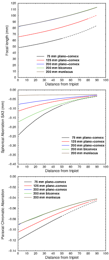
Fig. 5. Focus data for element #4. In the top and bottom graphs, the blue, green, and brown curves are superimposed. Only SA (middle) is affected by the type of lens. Dashed lines indicate distances that are unreachable because of the flip-up mirror.
What kind of bending should the focusing element have? As shown on the panel at right, a 75 mm DCX lens would not only be much too focusy, it would add back much of the SA that we tried to eliminate. Although it could give us a zoom from 48 to 80 mm, to do this it would have to be less than 40 mm from the sensor, which is closer than we can get on most DSLRs. The unreachable areas are shown by dashed lines. A 75 mm element would also produce a fair amount of vignetting. But even though we could probably never focus it to infinity, it would give us a terrific macro lens.
On the other hand, setting the focal length of element 4 to 125 or 200 mm gives us a zoom range of 65–92 or 82–115, as shown in the top graph at right. That may not sound like much in this age of ultra-zooms, but to get a wider range, we would need a more complex design.
The other question is: what type of lens should element 4 be: double, plano, or meniscus? The graphs at right show the type has no effect on focal length or CA, but it makes a big difference with SA. In our setup, a plano-convex would have less than half as much SA as a double convex lens. A meniscus would be about half of that, and it's the only one for which the SA is constant throughout the entire zoom range. So a meniscus is clearly the best choice.
Taking these factors into consideration, our final optical design is shown in Fig. 7. The triplet design reduces our SA and chromatic aberration to below 1 mm, and our astigmatism is below 0.2. Coma, as shown by the three graphs on the left, is also ten times lower than a lens made out of a single convex element. Compare this with an SA of 12 and astigmatism of 8 for a single element configuration in Fig. 2.
Our prescription is shown in Fig. 6. As an aside, it turns out that just by adding another element made of BK7, we can reduce the aberration by another factor of ten. Unfortunately, BK7 doesn't pass UV well enough.
In the prescription, the first column is the radius of curvature, the second column is the thickness, and the 3rd column is the aperture radius. The sign is + for each surface that is convex, starting from the front, and − for each surface that is concave. So a lens with +86.2 and −86.2 is a double convex.
To convert from curvature radius to focal length, use the formula

where Φ= power
n = index of refraction
t = lens thickness
and R1 and R2 = the front and back radius, all in millimeters.
Most people just use the thin-lens approximation

So the lenses I used are:
- CaF2 biconvex lens, f=100, d=25.4 mm (Thorlabs LB5552) (radius=86.2)
- Fused silica biconcave, f=−75, d=25.4mm (Thorlabs LD4735) (radius=−69.6)
- CaF2 biconvex lens, f=100, d=25.4 mm (Thorlabs LB5552) (radius=86.2)
For Element #4, I ended up using a f=200 mm d=25.4 mm planar convex, which actually was a little better than the meniscus, even though the meniscus had a lot lower spherical aberration.
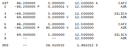
Fig. 6. Prescription
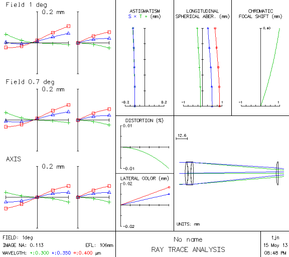
Fig. 7. Ray trace analysis of fused silica zoom lens (beam radius = 12 mm)
Click here for part 2: Construction
Click here for part 3: Test photographs
References
Warren J. Smith, Modern Optical Engineering, 4th ed. SPIE / McGraw-Hill, 2008
Warren J. Smith, Modern Lens Design. 2nd ed. SPIE/McGraw-Hill, 2005
