 ometimes even us lowly biochemists need to do fluorescence microscopy.
Unfortunately, a good fluorescence microscope can cost $30,000 or
more. Is it possible to use an ordinary inverted scope used for cell
culture to do fluorescence? In this page, we'll find out.

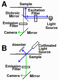
Fig. 1. Fluorescence microscope diagram. A: epifluorescence in standard fluorescence microscope. B: design using transmitted light
There are two ways of imaging fluorescence. Most microscopes use epifluorescence, in which the fluorescence is imaged from the same side of the sample as the light source (Fig. 1a). This requires dichroic mirrors, which reflect or transmit light depending on the wavelength. The alternative is to use transmitted light. For this to work, the excitation light must enter at an angle to the specimen to prevent the intense beam from entering the optical path (Fig. 1b). If it did, the strong incident light would contaminate the signal because optical filters aren't 100% efficient.
A good introduction to fluorescence microscopy can be found here[1]. I am not an optical engineer or a microscope expert. I used this device for a specific experiment, and it worked satisfactorily. If you find any inaccuracies in this article, please let me know.
Light source
LEDs are easy to work with and reasonably monochromatic. However, to work efficiently, they need to be focused into a narrow, collimated beam using lenses. Commercial collimated LED sources and controllers for Zeiss, Leica, Nikon, and Olympus microscopes are widely available. Collimation means the beam passes through lenses so it doesn't focus or diverge. This means beam radius doesn't expand (much) with distance.
Lasers have a narrower bandwidth, and they're reasonably collimated to start with, but the beam pattern from a semiconductor laser is not necessarily homogeneous. An optical diffuser adds speckle patterns and the unfocused beam may contain inhomogeneities and diffraction patterns near the edges of the field. For this particular laser, the beam width was 3–4 mm in diameter so a beam expander wasn't needed. Alternatives such as homogenizing light pipes are said not to be suitable for lasers, though I'm not convinced; a flat-top beam shaper, which costs around $5,000, may be needed if quantitative information is desired.
Safety
A laser with class 3B or above (>5 mW) is very dangerous to work with and requires an interlock to prevent accidental exposure. Even reflection from a specular surface is hazardous. (A near-infrared laser is even worse, as you can't tell whether you're being exposed to the beam until it's too late. Infrared-absorbing protective goggles are essential.) Don't try to make this device unless you have experience building optical devices and understand the risks and safety requirements. If you're at a university or company, your safety person will shut down your lab if they find a laser being operated unsafely.
Those high-intensity blue LEDs are no picnic either, and looking directly at them is strongly discouraged. Collimated LED sources in particular can produce permanent eye damage, but even uncollimated blue light might be hazardous with long exposures.

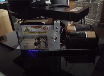
Fig. 2. Fluorescence light source installed in an inverted scope. The source sits on the microscope stage. Inside is a UV-enhanced mirror that deflects the light at an adjustable angle. In a darkened lab, some scattered light is visible around the sample, but the 100-mW laser itself is encased in a light-tight box with a safety interlock switch, and it is extremely bright
Optics and filters
For our el-cheapo fluorescence scope, we'll use an LED or laser, which eliminates the need for an excitation filter. The new light source is self-contained and sits on the microscope stage. The interlock prevents activation of the laser unless the unit is on a flat surface (Fig. 2).
A 1/4-inch piece of black opaque acrylic is attached to the stage. A 1-inch hole is drilled in the acrylic and an emission filter fits in the hole. The emission filter is an interference filter, so it must be oriented in the direction of the light, shown by an arrow or dot on the filter.
Results
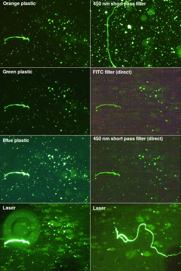
In this test, isolated cell nuclei or mitochondria from patients were encased in agarose and treated to release the DNA. The sample was placed in an electric field and the DNA was stained with Sybr Gold, which has excitation and emission wavelengths close to FITC (fluorescein isothiocyanate). If the test works, we should see a fuzzy blob known as a ‘comet’ to the right of each nucleus. I tested a variety of filters using light at at a 45° angle as well as two “direct” tests using filters placed in front of the original microscope light source, which was set to its brightest level. The results are shown in Fig. 3.
When illuminated at an angle, all the filters, including orange, green, and blue plastic, showed good signal and low background, but the DNA comet was not visible. Uncollimated high-power blue LEDs gave a useless bright blue background regardless of the angle. I haven't yet tested LEDs with a collimator. In “direct” lighting, where the light was directed at the stage from above, there was a bright green background and the samples appeared black. So on those two images, I set the microscope's light to DIC (differential interference contrast), where only indirect light hits the sample. The result was too faint to see in the eyepiece, and I had to enhance the contrast in software to see anything.
As seen in the bottom two panels, the laser worked quite well. The laser beam wasn't homogenized, so the background is uneven. On the image at the lower left, a big out-of-focus piece of dirt can also be seen. More importantly, the fuzzy DNA is now visible.
Disadvantages: it's harder to change the excitation wavelength. Sourcing the parts is time-consuming. Care is needed to create effective shielding and fail-safe interlock. A laser diode is easily damaged by electrostatic shock. Upgrading the light source by using a pre-manufactured laser module or adding a constant-current power supply and beam homogenizer would add considerably to the expense.
The inverted scope pictured here had visible amounts of field curvature and bad coma at the highest power (20×) due to optical limitations in the lenses, but it was more than adequate for low-power fluorescence.
About those fibers
Those fibers turn up all the time in samples. I first saw them in samples of cultured neuronal cells. They bear a marked resemblance to the “foreign objects” that people claim to have found in vaccine samples. They are not “worms.” After tracking down the source, I found that they're fibers released by sterilizing filters when a syringe pushes a liquid through them. They appear green here because they're stained, but normally they're transparent and sometimes tinted red, blue, or other colors.
If your sample isn't filtered, you get even more weird clumps and chunks of alien-looking stuff. An inexperienced colleague of mine once started writing it up, thinking those clumps were a big discovery. He just scoffed when I told him that his serum had to be filtered even though it was already sterile. Sterilizing is only half the battle: if it's been frozen, it's probably got junk like cryoprecipitates and little Bits O' Plastic in it.

Fig. 3. Cells labeled with Sybr Gold DNA stain. Regions containing a fiber were selected for comparison. These little fibers are not part of the sample but bits of cellulose that routinely fall off a sterilizing filter. They're often brightly colored. Conveniently, they're also highly fluorescent when stained for DNA. The two middle right panels (FITC filter and 450 nm short pass filter) have been contrast-maximized because nothing was visible in the original. These are old slides that have been sitting around for a while, and there is a certain amount of dirt on them, which appears as fuzzy out-of-focus concentric circles
1. Sanderson MJ, Smith I, Parker I, Bootman MD. Fluorescence microscopy. Cold Spring Harb Protoc. 2014;2014(10):pdb.top071795. doi:10.1101/pdb.top071795
nov 28 2021, 6:43 am. updated jan 14 2022
