
Improving and replacing the reticle in a polar finder scope

Polycarbonate polar finder scope reticle.
 chieving a good polar alignment is essential for preventing drift and
field rotation when doing astrophotography. Even if you use a computerized
mount with automatic star alignment, you still need to start out somewhere
near the North Celestial Pole (NCP). And because of those miserable things
known as "trees" and "houses," not everyone can use a computer to align
their mount. I've heard there are even a few crazy ones who actually
prefer to do all their alignments manually.
chieving a good polar alignment is essential for preventing drift and
field rotation when doing astrophotography. Even if you use a computerized
mount with automatic star alignment, you still need to start out somewhere
near the North Celestial Pole (NCP). And because of those miserable things
known as "trees" and "houses," not everyone can use a computer to align
their mount. I've heard there are even a few crazy ones who actually
prefer to do all their alignments manually.
From this point of view, using a computer to find things in the sky is cheating. It's like buying a postcard with a picture of the Washington Monument: it may be faster, but you've deprived yourself of the fun of spending two hours looking for a parking space, an hour finding the Mall, and three hours waiting in line to see the real thing. Much of the satisfaction in astronomy comes from the process of finding things. For me, that includes the NCP. In my tree-rich environment, I have to use a polar finder scope and do a drift alignment. But I'd do it that way anyway for the learning experience.
Unfortunately, most polar finder scopes these days are non-illuminated. This means you can't use them when it's dark, because you can't see the markings. You also can't use them when it's light, because you can't see the stars. What's more, adding a red LED doesn't help much, because the markings are simply printed on the reticle rather than engraved. The problem is that the chromium lettering doesn't scatter the light, and it's not reflective enough to make it visible in the dark. Yes, you can reach around and shine a flashlight on it from behind; or you could bounce the red light off your eye and illuminate it from the front. But neither of these methods work very well, and I would be concerned about the possible danger of shining a red LED, even a dim one, into your eye.
By making your own reticle, we can solve all these problems. Using a razor blade, we will make smooth lines in a piece of round polycarbonate. These lines act as prisms and reflect light toward the observer. You will still need the old reticle, along with a low-power microscope (or a magnifying glass holder and really keen eyesight), a carbide scriber ($7.22 at McMaster), a razor blade, and a piece of polycarbonate (Lexan, available from most hardware stores).
Below are instructions for making an improved reticle. Be forewarned, it takes a little practice to make one without scratching it up. The most time-consuming part is cutting the round shape. Unlike the commercial printed reticles, this plastic reticle works with a red LED. In fact, the lines are so easy to see, I can usually align the scope without any extra light, using sky glow alone (Oh, did I mention that my observing site sucks?).
Construction
These instructions apply to Celestron's polar finder for CGEM and CG-5 (part no. 94224), but should work for most other polar finder scopes if they're of comparable size. In this section we will use Celestron's reticle as a template, and simply trace the markings from Celestron's reticle. Later, we will use an improvement that greatly increases the accuracy.
- Remove the glass reticle from your old polar finder scope.
- Cut a piece of 2mm (0.08") clear polycarbonate into a square at least 17×17 mm. Do not remove the plastic protective coating from the polycarbonate. (The actual thickness of these sheets varies quite a bit. I have seen them as thick as 0.095 inches (2.4 mm) thick.)
- Use a fine-toothed saw (such as a band saw with a metal-cutting blade) to cut it into a round shape.
- Taking great care not to scratch the face, use a file to make the reticle as round as possible, and verify that it fits in the available space.
- Create a clean area near your microscope or magnifier and line it with a paper towel. Tape a piece of black paper to the paper towel.
- Take the old glass reticle and place a thin piece of transparent plastic, such as a clear sheet protector, over it. Tape the reticle by the edges using aluminum flashing tape, or press it into a piece of polycarbonate with a hole drilled in it to prevent it from moving. The sheet protector will prevent the glass from scratching your plastic reticle.
- Carefully remove the protective plastic from the reticle and place it precisely on top of the old reticle, and tape it down, being careful to avoid covering the printed areas.
Engraving the reticle
This part takes a steady hand and great care. Polycarbonate is quite tough, so there is no danger of cracking it, but it scratches very easily, so it should only be held by the edges. (Polycarbonate can be polished by briefly passing a propane torch over it. There is a better way of polishing polycarbonate, but it requires specialized equipment and chemicals and would not be worth the cost.)
- Gently press with the scribe to mark the positions of the stars. This will create a smooth round indentation that catches and reflects the light. Only a slight pressure is required. If you press too hard, the indentation will be too big, making it hard to align with the real star.
- Make a tiny mark at the NCP. Use a new single-edge razor blade and a steel ruler to draw a fine cross at the NCP through the tiny mark. If the razor blade is not sharp enough, it will make a ragged line instead of a smooth depression in the plastic.
- Draw a circle at Polaris. I happened to have a 1-mm lettering punch and used the letter "O". If you use this method, punch the letter before doing anything else, because it's quite difficult to hit the exact position with a punch. Although you can draw the circle freehand, a better way is to drill an appropriate-sized hole in a piece of thin metal and use that as a template.
- Draw the constellation lines using the scribe or a new single-edge razor blade and a ruler, taking great care not to scratch the reticle with the ruler.
- If desired, draw radial lines through each star. Don't extend these lines all the way through the NCP, or it will create a messy area in the center. There should be nothing in the center but a faint cross to allow you to center the reticle with the setscrews.
- Label the NCP and Polaris, and the constellations, if desired. I recommend using the scribe for this.
- Remove any fingerprints and tape residue using a microfiber cloth or, if that doesn't work, ethyl alcohol (NOT acetone!). Don't try to clean it with a Kleenex--it will become scratched.
Making glass reticles
Glass is harder than polycarbonate, making it more resistant to scratching. You can buy optical quality 17-mm diameter glass disks for $5 apiece. However, I didn't have much success engraving clean lines in glass. It's possible to create very fine lines using a carbide scribe or a Proxxon, but these lines are too fine to refract much light. Glass is too brittle to make deeper lines with this engraving technique--the surface tends to flake off, and you end up with coarse lines that are as much as 70 or 80 microns (0.003 inches) across--far too big for our purposes. Etching is the preferred technique for making glass reticles.
Installation
Install the new reticle in your polar finder scope. It will probably be necessary to re-focus the polar finder scope by unscrewing the primary lens in the finder and adjusting the locking screw. Next, use the three setscrews to align the reticle so that the NCP does not move when the mount rotates. (Use a distant target during the daytime). NOTE: The Celestron polar finder uses metric screws. Unified Thread size screws, which are used in the USA, won't fit.
Once it's installed, you can add a red LED to back-illuminate it. I tapped into the "Power" LED on my mount, ran the wires inside the mount, and used hot-melt glue to fix it in place. This saved me the cost of buying a current-limiting resistor. Hey, seven cents is seven cents. See here for how to calculate the value for the resistor you'll need if you use a battery instead.
The markings on the new reticle are infinitely easier to see than the ones on Celestron's reticle--so much so that I don't even bother with the LED anymore. When I get a chance, I'll post a picture here of the view through the polar finder. But it will have to stop raining first. So don't hold your breath.
Improvements
Even though the rough edges of our reticle made with a saw will be covered in use by the mounting screw, to give a more professional appearance we would like it to be perfectly circular. Here's how to make a round reticle blank without using an expensive cutting machine.

Reticle with radial lines for additional stars
- Cut a 3-inch piece of 1/2" diameter wooden dowel. The end must be perfectly straight.
- Put the dowel in the chuck of a drill (preferably a drill press or, better yet, a lathe).
- Run the drill at a moderately high speed, pressing the dowel against a file until there is no visible motion on the rotating surfaces, including the bottom. Don't remove the dowel from the chuck after doing this step.
- With a saw, cut the polycarbonate blank into some approximation of a circle, leaving the protective plastic layer intact.
- Without removing the plastic layer, apply a drop of hot melt glue to the dowel and attach the blank to the dowel, centering it on the end of the dowel.
- Run the drill at medium speed, using a file and sandpaper to turn the blank into a perfect circle.
Once it's finished, carefully remove the blank and peel off the protective plastic. The glue is automatically removed, leaving an unscratched, circular blank. If necessary, clean any dust and fingerprints off using a microfiber cloth (NOT a paper towel!)
It's easy to improve the reticle markings as well, by adding other stars. Because Polaris is not exactly at the NCP, you need at least one other star for a polar scope to get you closer than 3/4 of a degree. Unfortunately, neither Ursa Major nor Cassiopeia, which are marked in Celestron's polar finder, are actually visible through their polar finder. Therefore, it's impossible to know whether your orientation is correct. You can greatly increase the accuracy by marking the positions of real stars close to the pole that are visible in the polar finder. Since we don't know the exact magnification of the finder, the position of these stars could be indicated by a radial line instead of a dot. You can find the correct angle by printing out a small star map, drawing lines to the pole, and then placing the reticle on the map. These additional radial lines greatly increase the accuracy of your polar alignment. If you draw them accurately enough, they will reduce your drift alignment from a half-hour ordeal to a minor tweak that can be done in a few seconds. That makes it well worth doing.
Precession

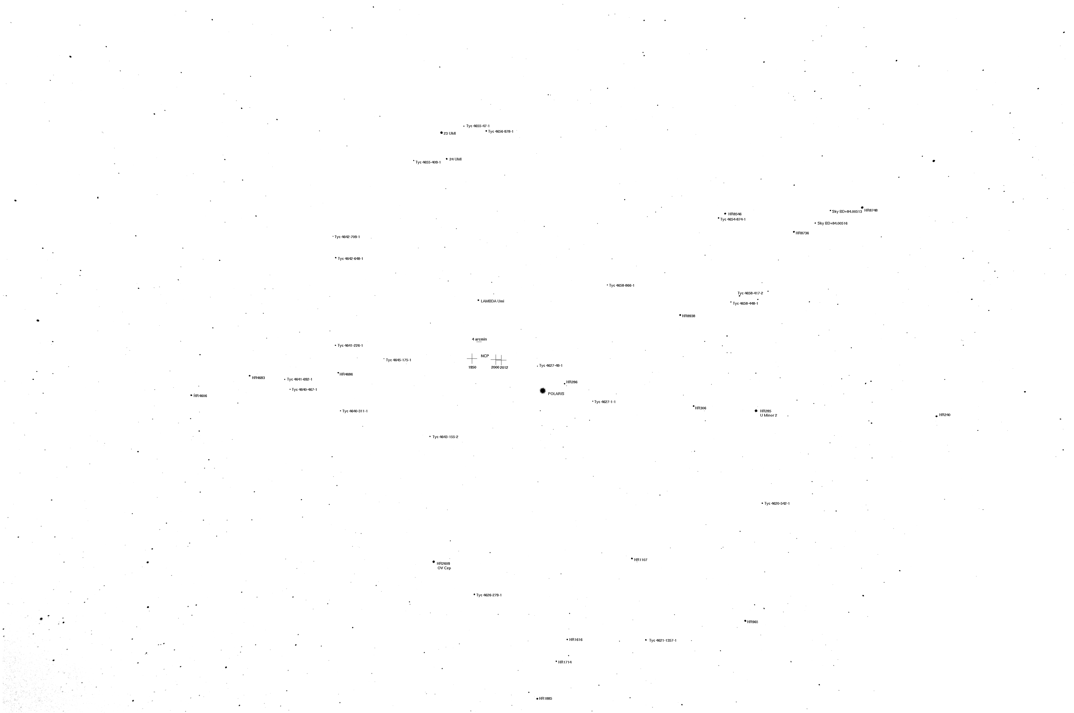
North Celestial Pole Map showing the relative distances from the 2012 NCP. The orientation will change depending on the season. The line to Polaris has been extended to make it easier to trace onto the reticle.
Polaris is currently 41.6 arcminutes from the pole. Due to precession, the position of the NCP changes by about 49 arcseconds per year. So the accuracy of your alignment will depend on how up-to-date your reticle is. Polaris is currently getting about 20 arcseconds closer to the North Celestial Pole per year. If your reticle was updated for Epoch 2000.0, that means the closest you can get to the pole in 2012 with your old reticle is 4 arcminutes. To achieve better than this, we need to take precession into account.
Since the reticle supplied with the polar finder is of unknown accuracy and age, we'll create a new one from scratch. Thus this procedure will also work even if you're making your own polar finder with a higher magnification. It requires access to a microscope and some careful measurements.
First buy, borrow, or create a measuring reticle and slap it in your polar finder. One solution is to use a copy machine to print a tiny ruler onto an overhead transparency sheet, but any transparent object with parallel lines will work. An even better solution is those linear optical positioner strobe strips found in VCRs, which are 350×4 mm transparent strips of acrylic with black lines printed every 0.166 millimeter (152 lines per inch). Everybody saves these, right?
The more stars you measure, the greater the accuracy will be. I tried this during a recent full moon, and obtained the following measurements (column 2 in the table below):
| Star | Distance to Polaris (Reticle units) |
Distance on Map (cm) |
Ratio | Corrected Distance to Polaris (Reticle units) |
Relative Distance to NCP from map |
Distance to NCP (Reticle units) |
|---|---|---|---|---|---|---|
| HR285 U minor 2 | 3.67 | 6.22 | 1.696 | 3.669 | 5.2452 | 4.5166 |
| HR1107 Cep | 3.30 | 5.55 | 1.682 | 3.274 | 4.7538 | 4.0935 |
| HR2609 OV Cep | 3.46 | 5.91 | 1.708 | 3.486 | 4.2652 | 3.6727 |
| U minor 24 | 4.39 | 7.33 | 1.670 | 4.324 | 4.1942 | 3.6116 |
| U minor 23 | 4.77 | 8.11 | 1.700 | 4.784 | 4.7251 | 4.0688 |
| HR8938 Cep | 2.64 | 4.60 | 1.742 | 2.713 | 3.6861 | 3.1741 |
| HR8546 | 4.43 | 7.40 | 1.670 | 4.365 | ND | ND |
| Polaris | 0 | 0 | - | 0 | 1.0000 | 0.8611 |
If viewing on a cell phone, drag table left or right to scroll.
With such crude equipment (the aperture is only 19 mm, and the field of view is nearly 10 degrees), these measurements will only be accurate within an arcminute or so. We're not doing precision astrometry here. But we can correct the distances by using a computer map, or even use a ruler to measure the distance on a map such as the one in Sky Atlas 2000.0. Averaging the ratios thus obtained gives our scaling factor, in this case 1.6953. This gives us the corrected distance in reticule units in column 5 of the table above.
Next we need the 2012 North Celestial Pole Map (shown at right) which shows the relative distances from the NCP (click here for higher resolution Adobe Illustrator format). On this map, we also measure the distance of one of the stars to Polaris. This gives us a conversion factor allowing us to calculate the distance from each star to the NCP in reticle units. In this example, Polaris to Ursa minor 24 was 5.0211 px in Illustrator, making the factor 4.3237 / 5.0211 = 0.8611.
To create the reticle, print out the NCP map and use it as a template to mark the angles of each star on the reticle. Don't draw the lines all the way to the NCP. If possible, also leave a small gap at the position where the star should be. Then, using your measuring reticle as a template, mark the star positions on the reticle at the distances in the last column of your table. A microruler would be a big help here if you want greater accuracy. Unfortunately, they're costly. I used a file to remove the sharp edge of a razor blade and engraved rulings on it at 200 lines per inch. (It turns out that this is one of those things you only do once!) If you make a ruler, steel is the material of choice because you can put much finer lines on it than on aluminum.
Notice that on Celestron's reticle, Ursa Major and Cassiopeia are printed on the opposite side from their actual location. The constellations are only there to orient you in doing a crude alignment. If you engrave them onto your reticle using the star map, they will be 180 degrees away from where you expect.
As an aside, the distance from the NCP to Polaris on Celestron's reticle was found to be 0.89 units, indicating that it was actually designed for the 2004 or 2005 position of the pole. This means it was already about 2.5 arcminutes off in 2012.
Parallax
Although you can use a paper map as a template, it creates the problem of parallax caused by the thickness of the polycarbonate. This makes it difficult to be sure your markings are correct. Here is the solution I finally used:
- Sharpen an ordinary sewing needle using a small grinder such as a Proxxon to make a fine point at the end, while observing it through the microscope. (If you only have a Dremel, you might have to modify it slightly to make it accurate enough.) A plain sewing needle is not nearly sharp enough for our purposes.
- Place a transparent plastic sheet protector over the map, and use the needle to punch tiny holes at the location of each star, using a microruler and the distances calculated above.
- Use a Proxxon or Dremel with a thin cutting wheel to create a marking tool with from a single-edged razor blade. The marking tool consists of a sharp edge about 2 mm long with a 0.3 to 0.4 mm gap in the center. A microscope is necessary to make this tool. Use goggles!
- Tape the plastic sheet protector template on top of the polycarbonate reticle. For each star, press down through the sheet protector with the marking tool. Then rotate the tool 90 degrees and repeat, to create a pattern of four lines pointing away from each star.
- Use a single-edge razor blade to make a very fine cross at the NCP, and use a carbide scriber to label the stars. This is not as easy as it sounds, because you have to draw letters that are about 0.35-0.4 mm tall. I used a Dremel 1/8-inch 9909 tungsten carbide cutter that had been sharpened to a fine point with a micro-grinding wheel. The tip is almost, but not quite, fine enough to use as it is.
This avoids the need to make small dots in your reticle, and greatly reduces the amount of scratching caused by the microruler. It also eliminates parallax error caused by the thickness of the polycarbonate. The reticle shown at the top of this page was made using this technique.
Creating a reticle on an optical bench
Unfortunately, no matter how carefully you measure the star positions on your reticle, there is almost always some error, which results in one or two stars that don't line up precisely with the sky. One way of avoiding this is by using an actual photograph of the sky as a template. We will project a beam of light through the polar finder itself onto the photograph and mark the star positions visually instead of using a ruler. Although this method takes a lot longer to set up, engraving the reticle is much faster, and requires only a single measurement. The result is a reticle in which any optical distortion in your polar finder scope is automatically cancelled out.

Crude optical bench for making reticle
- Remove the eyepiece and the original reticle from your polar scope and mount them in such a way that you can focus a beam of light through it onto a white screen behind the eyepiece (see photograph). Use lots of clamps--the setup must be perfectly rigid.
- Use a digital camera to take a photograph of the polar region, with about a 10° field of view. On a computer, convert the image to a black-on-white map and print out a copy. Or, use this one.
- Mount a blank rectangle of polycarbonate between the lenses so it's in focus and any markings on the polycarbonate will be projected onto the map. Make sure that you can still access the side away from the map with a marker or engraver. (If you mark the other side, it will still work, but you'll have to draw the labels as a mirror image.)
- Make two marks on the polycarbonate some specific distance apart (such as the distance between Polaris and Ursa Minor 2 in the table above), and adjust the position of the map so that these marks line up with the corresponding stars.
- With a razor blade, draw a fine cross somewhere on the polycarbonate rectangle and align the projection of the center point of the cross with the NCP (or SCP) on the map.
- With an engraver, make a tiny mark for each star, using the shadow of your engraver on the map as a guide. This can be a little tricky because the projection will be inverted. However, it's much faster than using a ruler and template because you don't have to measure anything. If you make a mistake while marking the star positions, you can just move to a fresh area of polycarbonate and start again.
- Remove the polycarbonate and draw guidelines or circles around each mark if desired.
- Carefully use a band saw to cut the polycarbonate into a 17 mm diameter circle and slap that baby in.
Down Under
Another improvement, for those living in the Southern Hemisphere, is to create a reticle using Octans, and leaving off Cassiopeia and Ursa Major, which only serve as additional distractions. For those living Down Under, accounting for precession is the least of their problems. To see the universe in the correct orientation, those poor devils also have to do their astronomy while standing upside-down.