Shortwave ultraviolet photography
 aking pictures at wavelengths below 300 nanometers is much more difficult
than near-UV photography. A fused-silica / calcium fluoride lens is essential,
because glass absorbs all light below about 330 nm. A fully
modified camera, which has the UV-absorbing
filters removed (or an astronomy camera, which doesn't have them) is also
essential.
Shortwave UV photography is also hampered by the low sensitivity of frontside illuminated CCD and CMOS sensors in the UV, and by the fact that there's actually very little short wavelength UV (UV-C) out there, even in bright sunlight. I installed a 1-inch 253.8 nm filter in my homemade CaF2 / fused silica UV lens attached to a UV-modified D90 and went outside to take some pictures. Even with 30 second exposures, all of them came out completely black except for brightly sunlit scenes. Most ordinary objects appeared black except for the sky (Fig. 1).
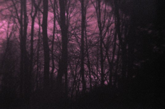
Fig. 1. Shortwave UV photo of outdoor scene taken through a 253.8 nm, 10 nm bandpass interference filter in a modified Nikon D90 DSLR (1:37 PM, 24 sec, ISO 1600, homemade UV lens).
With an artificial light source, it was a different story. The photo below (Fig. 2) shows from left to right a “black light” bulb (max=365 nm), a cool white bulb, and an unfiltered mercury germicidal bulb (max=254 nm). The blacklight appears red, which means that what we're seeing is mostly 365 nm light leaking through the filter. The cool white lamp is completely black except for a reflection of red on the left side, and the germicidal lamp is intense white but appears out of focus.
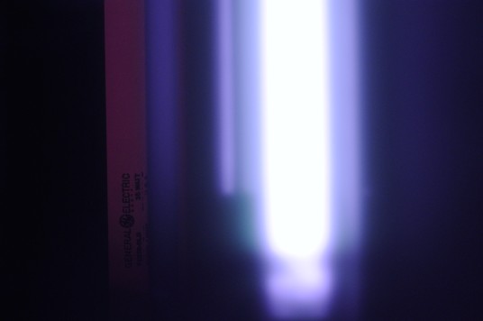
Fig. 2. Shortwave UV photo of blacklight bulb (left), cool white fluorescent bulb (black area in the center) and germicidal mercury vapor lamp (right) taken through a 253.8 nm, 10 nm bandpass interference filter in a modified Nikon D90 DSLR (30 sec, ISO 1600, distance 3 meters).
A convenient way of testing whether you're really detecting shortwave UV is to hold a piece of ordinary glass in front of the lens. When I did this, the white portion from the germicidal lamp disappeared, but the red from the blacklight was hardly affected. This proves that the red color was contamination from 365 nm light getting through the filter, while the blue-white was shortwave UV. This proves that the sensor is not just an inert lump of metal at 254 nm, as one person called it, and it should be possible to use it for shortwave UV photography.
However, I was never able to get the germicidal lamp into sharp focus with this setup, even from 12 meters away. According to the computer, this can't be due to spherical aberration in the lens (OSLO says SA3 should be −0.02 at 254 nm, which is reasonably good for UV). The problem is that the glass that protects the sensor is opaque to these wavelengths.
At near-UV wavelengths, shorter λ shows up as an increase in the red to blue ratio (Fig. 3), as discussed here.
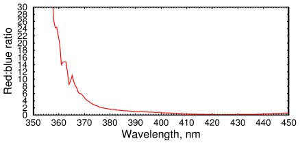
Fig. 3. Red : blue ratio for ultraviolet in a modified D90 measured from images of a quartz-halogen lamp.
At wavelengths below 330, the ratio decreases again, and images start to appear yellow and eventually bluish white. At short UV wavelengths, the Red/Blue ratio changes back toward blue, and some signal reappears in the green channel (R:G:B = 11:9:26 at 254 nm).
Quartz halogen lamps produce a little UV, so I tried photographing one. I got a nice sharp image ... but it too failed the glass test, meaning it was contamination leaking through the filter.
Shortwave UV light is harmful to your skin and especially your eyes. Polycarbonate face shields and long-sleeved clothing are recommended. Polycarbonate eyeglasses give better protection than glass lenses (Fig. 4), but watch out for reflections.
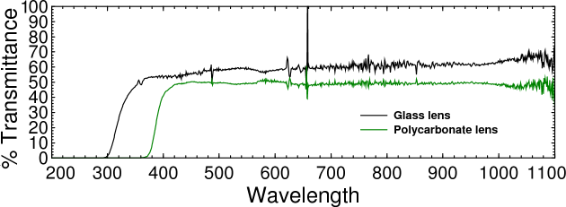
Fig. 4. UV-Visible-infrared spectra of plastic and eyeglass lenses. Plastic lenses cut off more ultraviolet than glass. Transmission is lower than you might expect because the lenses are concave. Both types give your eyes some protection, but only a face shield protects against reflections.
Interference filters with bandpass below 300 nm are hard to find. Filters with shorter wavelengths also have less throughput than long-wavelength filters. All three filters had absorbances ≥4 outside of their passband. But with conventional frontside illuminated sensors, that may not be enough.
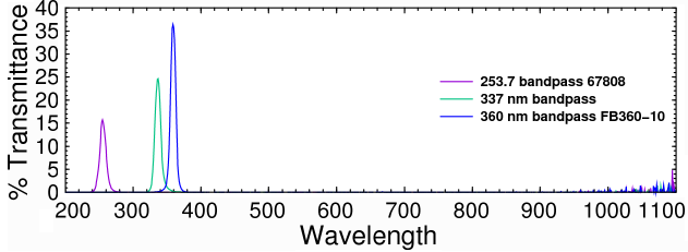
Fig. 5. Transmittance spectrum of Edmund Optics 67808 253.7 nm UV filter, 337 nm filter, and Thorlabs 360 nm filter.
Astronomy cameras
Monochrome astronomy cameras have two advantages over a DSLR: they don't need to be modified to photograph ultraviolet light, and they're designed to expose for hours if the subject is dim. Of course if your camera has a filter wheel, the filter needs to be removed. I tried an SBIG STF-8300M astronomy camera and got images, but there was no improvement over the DSLR.
The Sun is a good source of shortwave ultraviolet light. A typical exposure time was 1/15 second. Clouds blocked most of the shortwave UV (by scattering it), and it was necessary to expose for up to 1/2 second when it was cloudy (Fig. 6).
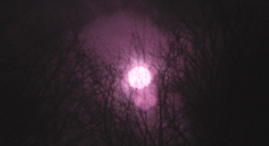
Fig. 6. Shortwave UV photo of the Sun taken through the clouds with a 253.8 nm, 10 nm bandpass interference filter in a modified Nikon D90 DSLR (1:11 PM, 1/2 sec, ISO 1600, homemade UV lens). The Sun never gets above the trees around here in the winter.
Shortwave UV photography has many potential uses. DNA and proteins all absorb at these wavelengths. This makes shortwave UV photography useful to forensic photographers, because latent fingerprints contain small amounts of protein. Aromatic compounds like benzene also have good absorbance around 260 nm. At shorter wavelengths (below 230 nm) ordinary unsaturated lipids begin to absorb, which makes this region ideal for finding fingerprints. But an artificial light source is essential. At such short wavelengths incandescent lamps don't provide much intensity. Commercial spectrometers use either xenon arc lamps or deuterium lamps, which are very expensive.
This is not to be confused with fluorescent UV photography, which uses a UV source and captures the visible fluorescent light. Photographing fluorescent objects under UV is much easier than trying to capture an image in the shortwave ultraviolet light itself.
Before proceeding any further, we need to know whether the sensor has enough efficiency in short wavelength UV to make it worth considering.
Quantum Efficiency
What quantum efficiency can we expect at 254 nm? Quantum efficiency is determined by how far a photon gets into the photosensitive region of a chip before being reflected or absorbed. Most commodity-grade CCD chips are frontside illuminated, which means the photon must cross a polycrystalline gate layer to reach it. This makes it easy to estimate what the QE should be for any given wavelength.
Janesick [1] gives a formula for CCDs. It's only a rough estimate for us, because CMOS sensors are not as linear as CCDs [2]. We also have the complication that the Bayer filter dyes in color cameras are designed to reject UV light. But the SBIG camera uses a frontside illuminated CCD chip, and we know the absorption depth in silicon is around 60 Angstroms at 254 nm, so we can get an estimate using Janesick's formula

where
CCE = charge collection efficiency (assume 100%)
RREF = reflection coefficient of silicon at 254 nm = 68%
xpoly = polysilicon gate thickness in μm (assume 0.02 μm)
xepi = epitaxial thickness in μm (assume 0.4 μm)
LA = silicon absorption depth in μm (= 0.006 μm)
where we guessed at the thicknesses by back-calculating from the published specs on the KAF-8300. We get
QE = (1−0.68)exp(−0.02/0.006)(1−exp(−0.4/0.006)) = 1.1%.
So we should expect exposure times to be 50–100 times longer than for green light. But this doesn't consider the cover glass (Schott D263T eco), which cuts it down by at least 100-fold more below 300 nm. So it is clear that we need more modifications to the camera before starting. Scientific cameras with backthinned CCDs are very expensive (around $35k), but one vendor sells no-coverglass cameras with fused silica windows and no microlenses. They cost about twice as much as a regular astronomy camera, and you take a big hit in the visible and IR (only 10% QE at 500 nm).
Astronomy cameras typically have a chamber in front of the sensor to protect it from condensation. The chamber window may be glass, silica, or sapphire. To be useful in short wavelength UV, the cover glass attached to the sensor would also need to be made of UV-transmitting material.
Removing Bayer matrix and microlenses
Based on the calculations above, to get good sensitivity to shortwave UV, we need to remove the cover glass and ideally the Bayer color filter array (CFA) and microlenses from the sensor. This would also convert the camera to grayscale and increase the resolution. One poster on Stargazers Lounge was successful in removing the CFA from a Canon 1000D sensor. I bought a used Nikon D200 for about 100 bucks with the intention of de-bayering it. This camera has a CCD sensor, which is preferable because a CCD has a bigger photosensitive area and thus would give good sensitivity even after the microlenses are removed. It is a very risky procedure and it's advisable to practice with a webcam before trying.
Here is what we will do:- Practice by dissecting a webcam.
- Remove the protective cover glass of a CCD sensor.
- Remove the CFA and microlenses (if present).
- Coat the sensor with a phosphor.
- Pray it still works.
De-Bayering a webcam
Items needed:- Webcam such as a Logitech C270
- Fresh single-edge razor blade
- Butane microtorch with soldering iron attachment
- Microscope
- 3-inch piece of 20-gauge uncoated copper wire
- Spray bottle containing water
- Acetone
Step 1. Remove the circuit board and lens from a webcam. Put on a
grounding strap—these webcams are easily fried by touching them.
Step 2. Remove the protective glass flter as described
here. In a Logitech 270, the filter is embedded in
the black PVC plastic that protects the sensor. Create a groove around the
outside of the filter by melting the black PVC plastic with a soldering iron.
Without touching the glass, use the razor blade to cut a narrow trough on all
four sides of the filter. The glass will eventually come loose and fall out.
The trick is never to put any stress on the glass, or it will break.
Step 3. Make sure the webcam is unplugged and put a drop of water
on the sensor. The original poster used Meguiar's ScratchX, but I found this
only makes a mess. The CFA is not acrylic and cannot be removed with organic
solvents such as 1,2-dichloroethane or acetone.
Step 4. Silicon is reasonably hard (5–12 GPa), but depending on the
architecture
there could be aluminum masking and metallic bus lines, and the polysilicon gates
can be easily scraped off.
With a soft implement such as a copper wire or a piece of hard
plastic (not steel!), scrape off the CFA and microlenses. Scrape side to side,
not back to front. Underneath the CFA is a thin clear coating that should
also be removed. The bare sensor is a smooth gold-colored metallic layer.
Be careful not to scratch it, or you will create horizontal defects in the
image (Fig. 6). Don't try to scrape to the edge, or you might remove some of
the blue/green coated material or the metallic border around the sensor area.
The blue protects the fine circuit traces on the sensor. If it's damaged the
sensor will break after a few minutes of use. Don't touch the gold wires
around the edge.
Step 5. Spray the sensor with water to remove the dirt, then wash with
acetone several times. The acetone will wash away the water, allowing the
chip to dry by evaporation. Hold the chip at a 90 degree angle so the acetone
runs off. Let the acetone evaporate overnight before testing it.
Step 6. Make sure the webcam still works. The images should be pink
and smoother than before. The image below (Fig. 6) shows that the result looks
like a Rothko painting.
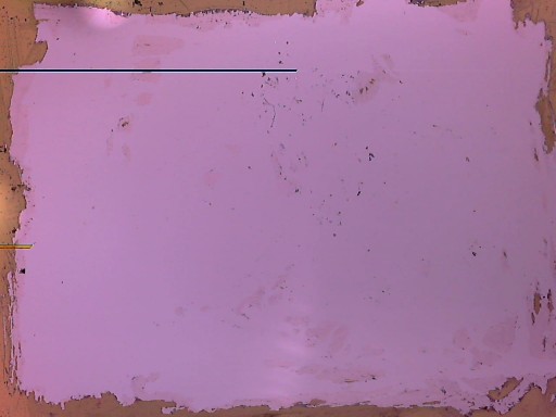
Fig. 6. Image from a webcam after removal of color filter array, cover glass, and lens. The black horizontal line indicates a scratch in the sensor. Some bits of the clear coating under the CFA are still present (lower right). I call this image “Pink and Brown De-Bayered Webcam Sensor Image No. 25.”
We could stop here, but to get the full resolution you need the raw image before RGB interpolation is done. Otherwise, every four pixels will be averaged together. It's not easy to get a raw image out of a webcam. Also, unlike a CCD, only 30% of the surface area of a CMOS chip is photosensitive. A CMOS sensor relies on the microlenses to bring the QE up to a reasonable level. So the next step is to de-bayer a CCD sensor. The last Nikons that used a CCD were the D80 (CCD = Sony ICX493AQA, the same as in the QHY10 astronomy camera) and the D200 (Sony ICX483AQA). A used D200 can be obtained for just over a hundred bucks, so that is what we will try first.
Converting a Nikon D200 for Ultraviolet Photography
The D200 was a good camera in its day, but the construction isn't as refined as later ones like the D90. Disassembling it is therefore a little more difficult. Some of the screws are hidden under the rubber grips, and you need a soldering iron to remove the shield that covers the circuit board. You also have to worry about several small gray shielded wires under the circuit board. I had to pry off the bottom panel with a screwdriver, since there was one screw that I could not find.
The blue IR-block / color correction filter in the Nikon D200 came out easily. After it was removed, the sensor had much better sensitivity in the infrared than the D90's CMOS sensor, and the IR leakage from my UV filter was now a potential problem.
The CCD was protected by a 24.5 × 32 × 0.7 mm piece of glass that was firmly epoxied down. After several minutes of heating it with the flame of a butane microtorch, the glass eventually separated from the base, but it still remained firmly attached. The only way to get it off was to spray water on it, which made the cover glass crack and fall off cleanly in small pieces. The water also helped extinguish the fire in the sensor base which was caused by my over-enthusiasm with the butane torch.
Luckily, after the smoke cleared and after the camera was dried and reassembled, it still worked perfectly, although the images now had fine vertical stripes in them, presumably caused by overheating. There is no doubt that the only reason it still worked was the micro-soldering iron and the big pile of electronic parts and disassembled optical components from another camera nearby.
Even with the lens adjusted to telephoto focal length, I was able to get a reasonably sharp photo of the Sun at 254 nm (Fig.7) with only a 1 second exposure despite a very hazy winter sky. However, a lot of longer wavelength light still got through the filter, as shown by the image on the right, where I blocked the UV below 300 nm with a piece of ordinary glass. This means the sensor is still not sensitive enough.
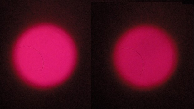
Fig. 7. Shortwave ultraviolet photo of the Sun. Left = 254 nm UV filter; Right = same filter, but wavelengths below 300 nm blocked with a piece of soda-lime glass. (CaF2/silica UV lens, modified Nikon D200, 1 sec)
Even so, the unblocked image on the left is clearly slightly bluer in the center. Due to the peculiarities of the sensor dyes and the filter, blue means shorter UV wavelengths, and red is longer wavelengths, mainly around 365 nm. This is consistent with the known fact that less UV is visible in the limb than on the center of the solar disk.
Subtracting the two images gives an image of the Sun at 254 nm. Maybe it won't win any awards, but we have to remember that almost all the shortwave UV from the sun below 280 nm is absorbed by the ozone layer.
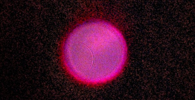
Fig. 8. Shortwave ultraviolet photo of the Sun after subtraction of the wavelengths above 300 nm. Contrast was increased by 4×.
But it's clear that, although we get more sensitivity, removing the cover glass from a sensor isn't making the UV images any sharper. Adding a second filter might get rid of the out-of-band radiation, but it would also reduce the transmittance from 15% to (0.15)2 or 2.25%.
To be continued ... I am not giving up ...
References
[1] Janesick, J.R., Scientific charge-coupled devices, p. 173.
[2] Fowler, B., et al. A method of estimating quantum efficiency for CMOS
image sensors. Proc. SPIE, 1998.
PDF
