
Repair notes for Spex Fluorolog 2 Fluorescence Spectrometer
This page contains information we discovered when repairing our Spex
Fluorolog 2 spectrofluorometer (model no. CM1T11I) in room 341. Although
this is a fine instrument, it is almost 20 years old and the technical
support people at the vendor are no longer able to repair it or provide
information about it. However, we were able to repair it on our own. The
purpose of this document is to serve as a reference for when the chewing
gum and twine wear out, and we have to repair it again.
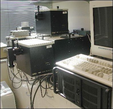 |
| Fig. 1. The dual emission version of the Spex Fluorolog 2. |
Jumper settings and I/O connections
The controller that comes with the Spex contains two CTI cards and two high voltage cards. Some models may have only one of each. The CTI card has digital I/O ports along the top, and two DA15 connectors on the back for analog input from the photomultipliers. One CTI card is needed for each emission monochromator / photomultiplier combination. If there are two CTI cards, all the I/O connections are made to the master card, and the two cards are connected by a short jumper cable. Jumpers J1 to J9 on both cards must be properly set for the cards to work.
The high voltage cards supply 950 and 400 VDC for the photomultipliers.
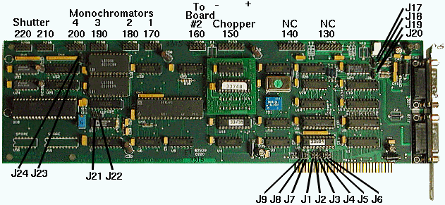 |
| Fig. 2. Spex CTI card |
- The I/O connections at the top of the card are made through the blue plastic connectors (See Fig. 3) to DE9 connectors on the back of the computer. Do not connect the blue cable from card 1 to card 2 upside-down, or it will blow out the card.
- Older cards have numerous fuses on each card. These are small white squares with a thin wire visible through a window. They are easily blown, and blowing a fuse is a common source of problems. These fuses can be safely replaced with wire jumpers. On later cards, these fuses were replaced by wire jumpers.
- The monochromators are 1681B single-grating monochromators. When powered on, they supply a potential of 3 volts to the blue connectors on the CTI card. The monochromators should be turned off before connecting or disconnecting cables to the CTI card.
- The blue connector for the shutter at locations 220 and 210 should be aligned to the far edge of the card. The number of pins on the card does not match with the connector. When the spectrofluorometer is first powered up, there should be an audible click from the shutter if the card is functioning.
- If there are two CTI cards, one must be set to Master and one set to Slave. Setting jumpers 9,8, and 4 makes it a master. Setting jumpers 9 and 7 makes it a slave. This also sets the IRQ to 5. If the IRQ is wrong, or if both cards are set the same, the software will either hang, or it will say "CTI board interrupt timeout error." The boards can be in any slot; as with any ISA card, moving to another slot is unlikely to fix a problem.
- The IRQ is set by jumpers on the CTI card. It must match the PC Interrupt line setting in hardware.ini and the IRQ setting in the BIOS.
- Both of our CTI boards are only partially functional. If a board does not cause the shutter to click, it still might be able to control the monochromators. Do not swap the boards on the Spex in room 341.
- Make sure the CTI boards and power supply cards are not touching each other. This can cause the board to short out. We placed a sheet of cardboard between them to prevent contact.
|
|
Newer versions
Later versions of the Fluorolog had the CTI and power supply cards in a separate box along with a PC-AT power supply and the Spex power supply. The box was connected to a PC by a pair of PC/AT bus expansion cards attached by a 62-pin three-row connector and a short cable. Although it is unmarked, most likely it would be a bad idea to disconnect this cable while the power is on.
The board layout is almost identical to the older versions. These old ISA boards use leaded components, which makes them easy to repair, if you can get the parts. Below is an image of the newer CTI card showing the jumper positions and connections for a system with a single card. P170, P180, P190, and P210 are connected to the monochromators and shutter using blue cables leading to DE9 connectors in the back.
A common fault with these cards is corrosion at the points where the fuses were replaced by short pieces of magnet wire, as can be seen here. The most common failures on any ISA board are corrosion at the connectors and cracked solder joints.
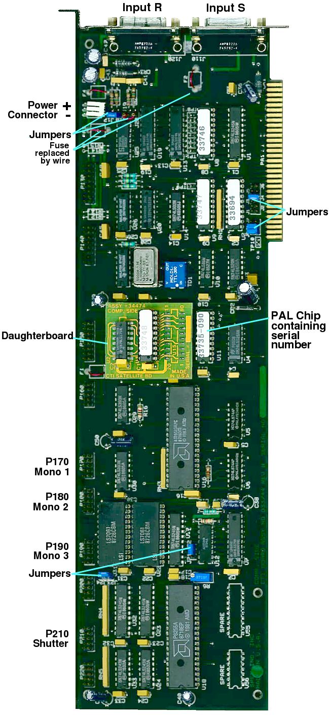 |
| Fig. 3. Newer version of SPEX CTI board |
DM302 and DM303 acquisition modules
The signals from the photomultiplier tubes pass through a DM302 P.C. acquisition module (pulse input board) which cleans up and amplifies the pulses. The only IC in this little box is an LM733CN wide-band differential amplifier.The four-pin connector is wired as follows:
| A | B | C | D |
| Ground | −12 V | + 12 V | not connected |
Signals from the reference cell pass through a DM303 D.C. Acquisition Module which contains logic circuits as well as a voltage-to-frequency converter chip. Pins 1 and 2 on the power connector supply +15 and −15 volts. The other pins are connected to the board and presumably used for something, but I haven't tried to trace the circuit to deduce their function. Most likely, they allow the software to set the data acquisition rate. The board only has an AD524CD precision amplifier, flip-flops, a SN7416N hex inverter buffer chip, a VFC, and two 831A-4 relays.
Update: Dan Wahl reports that the gain is changed by the three control lines. One is a strobe and two are select lines.

|
| Fig. 4. Spex DM302 and DM303 |
External Cabling
Cabling is fairly straightfoward. The PMT tubes have two different incompatible types of BNC connectors: a regular BNC and a special high-voltage BNC. Even though some of the cables resemble computer cables, there are no serial or USB protocols. On early SPEXs, these cables all plugged directly into connectors in a PC. Later models had a separate box which was connected to a PC by a heavy 62-pin bus extension cable. Almost every component has its own on/off switch and power cable. The lamp AC plug does not need to use a heavy cable, because it is only used for the fan.

|
| Fig. 5. External cabling |
Internal Wiring
The Spex 15/30VDC power supply is mounted somewhere inside the PC. In the original SPEX's, AC power was tapped from the PC's power supply as shown in Fig. 6. Four small cables come out from the Spex power supply and connect to the CTI cards and HV cards.

|
| Fig. 6. Power supply connections |
The connections to the CTI card are as shown in Fig. 7 below. The leftmost pin on the monchromator cables is a darker shade of blue. This wire is cut before it reaches the DE9. The remaining pins are connected as shown. The chopper cable is gray with one blue stripe and two red stripes. On the shutter cable, all the wires are the same color. The shutter cable is aligned on the leftmost pin. The correct orientation is with the dark blue wire on the left and the cut ends of the cables pointing up.

|
| Fig. 7. CTI board connections |
Software
-
At least some versions of the DM3000 software check the serial number on the
CTI board. If the board is changed, it will say:
The software then says:Serial number(s) on interface board(s) do not match the expected values.
and dumps you to a DOS prompt. According to the Horiba service rep, a hardware key is a serial number that is encoded in a PAL chip on the CTI board. In other words, the board has a form of copy protection that makes it difficult to repair the spectrometer. The vendor expressed surprise when asked about this feature, saying it is not present in more recent versions of the software. We could find no way to specify the board's serial number in any of the configuration files or in the dm3000 program itself. Bypassing the hardware check would require disassembling the dm3000 software.Hardware key does not return proper value. Please check your printer for error conditions. Access denied.
Update: Dr. Al Marchetti of the University of Rochester reports that the serial number is in the PAL chip labelled 33735. If you move this chip to a new CTI board, the old software will now recognize the new board. - The software was originally supplied on 5¼" floppy disks. All floppy disks become unreadable over time (as have our original floppies). Be sure to make copies on a more up-to-date medium.
- Our system had two different versions of dm3000.exe that were in different directories. It seems to have been common for users to have two or three different copies of DM3000, only one of which works.
A Short Primer on MS-DOS
Many younger people have never heard of MS-DOS, which was the precursor to Windows. MS-DOS was a minimalist operating system that allowed programmers to interact directly with the hardware. In fact, many programmers bypassed MS-DOS most of the time and sent assembly language commands directly to the hardware, because DOS was somewhat inefficient. To repair a Spex, it's necessary to understand how MS-DOS and early PC hardware works.
-
MS-DOS was entirely text-based. Programs were started by typing the name of the
program on the command line. In MS-DOS, unlike Windows, there is no "Registry."
Device drivers were loaded by including the name of the driver in a text file
called CONFIG.SYS.
Another text file, called AUTOEXEC.BAT, contained a list of
programs or commands that were automatically executed when the computer boots up.
These two files had to be in the C:\ directory.
For example, if you had a mouse, it would be necessary to have either a line in CONFIG.SYS called MOUSE.SYS or a line in AUTOEXEC.BAT called MOUSE.COM or MOUSE.EXE (or something similar) before the operating system could recognize the mouse. Each software program had to include its own programming for controlling the mouse and handling mouse clicks, as well as for other basic operations such as identifying the hardware, setting the graphics screen mode, and setting pixels.
For example, here is the config.sys file that we used in our Spex:
Here is our autoexec.bat:device=c:\dos\himem.sys device=c:\batch\chopoff.bin buffers=30 files=30 shell=c:\command.com c:\ /e:512 /p
Putting "rem" at the beginning of a line converts that line into a comment, which causes the operating system to ignore it. Note that MS-DOS, like Windows, ignores case.echo off prompt $P$G path c:\batch;c:\dos;c:\;c:\nshell;c:\spex250 rem print /d:LPT1 prtscrn doskey mousesys generic rem cls rem system cd spex250
- Early ISA cards had jumpers that selected the IRQ, which is a number between 0 and 15 indicating which hardware interrupt line (actually a pin on the CPU) was used to control the card. For these cards, it is necessary to go into the BIOS and specify a fixed IRQ for the ISA slot the card was in. Each device (card, disk drive, etc) must have a different IRQ to prevent conflicts. Some cards also used DMA, and had additional jumpers to specify the DMA channel. Cards occasionally came with a manual or a sticker that told you what the jumper settings did, but often the IRQ had to be found by trial and error. Computer repair people developed an intuition about which IRQ was likely to be used. For example, our CTI cards all used IRQ 5. Later ISA cards did not require jumpers or static IRQ settings.
- The Spex software also uses several other application-specific configuration text files to store instrument parameters. These parameters must be correct for your system. The number of CTI cards in the computer, as well as the IRQ that is used for the card, and a number of other important parameters, are specified in the hardware.ini file. The number specified in "PC interrupt line" section of this file has to match the BIOS settings on the computer. The other settings in the hardware.ini file must also match the Spex hardware, or the software will give an error message or (more likely) hang.
- There are a number of other files that are necessary, including program.ini, which sets the EGA mode graphing parameters.
-
In addition to an IRQ, software that acquires data also needs an I/O address,
which is the point in memory (specified in hexadecimal) where the software could
put parameters that were used by the interface card. The interface card would automatically
put its data in a block of memory starting at or near that I/O address. For example,
to set a pixel, you would simply send a specific byte to a particular offset from
the video I/O address. The contents of the screen could always be found by reading
the data from the video card's I/O address. (Later on, this became more complicated,
when banked video memory was invented.)
To find out if a specific card is installed, you would
put a specific byte to some other address. The card would automatically respond
by putting specific information at a certain offset from that I/O address.
Spex provided a driver called CHOPOFF.BIN that performs this function. If
CHOPOFF.BIN is loaded in config.sys, it prints out the I/O addresses of each
CTI card. This is helpful in determining whether the software is seeing the cards.
As far as I can tell, this driver appears to serve no other function.
On our system, chopoff.bin prints the following:
This is an important clue. If it doesn't print a reasonable address, you have to adjust the BIOS settings or the jumpers on the card until you see it. You may have to edit the autoexec.bat file to get rid of that menu program to see this.CTI Board found at 0220 CTI Board found at 0620
1681B Monochromators
Each monochromator has its own power supply, which is fed to the CTI card through a cable that resembles a serial cable. It is not a serial cable, however, and substituting a conventional serial cable may or may not work, depending on how it's wired. The CTI card makes contact closures that turn a stepper motor in the monochromator. Inside the monochromator, the motor is connected to the power supply by an 8-pin nylon connector. The eight pins connect to each end of the four coils in sequence (i.e., 1,1,2,2,3,3,4,4). There is no common wire. On the DE9 end of the serial cable, pin 4 and 5 should have 2.4 volts with respect to pin 3, pins 6–9 should have 3 volts with respect to pin 3, and pins 1 and 2 should have 0 volts with respect to each other. A sequence of momentary contacts between pin 3 and pins 4–9 rotates the motor.
The monochromator should move back and forth when the software starts up, before the software asks for the starting wavelengths. If the monochromator does not move, the board is not functioning.
Replacing the computer
The most common repair on the Spex is replacing the PC that acts as a controller. Computers with ISA slots are now only available as "industrial computers" from several Internet vendors for about US$ 1000.
We replaced our original PC with an RSI 4U rackmount system (Fig. 1 at right) with 9 ISA slots, from www.interloper.com. This vendor is highly recommended. Their technical support and service were excellent. The quality of the PC that we purchased from Interloper is much higher than the original PC-AT that came with the spectrometer.
Building a controller
Many people ask whether it is possible to eliminate the Spex controller entirely and create a new one. Building a new controller should not be too difficult. If you replace the controller, you will need a programmable high voltage power supply for each of the PM tubes (there are either 2 or 3, including the rhodamine reference cell inside the sample compartment). The machine itself is all transistors and analog components. Even though the cables resemble serial cables, there is no serial protocol between the controller and the Spex, and no digital commands to worry about--only contact closures and pulses from the photomultipliers. The monochromators don't have any digital stuff in them at all, and neither does the sample compartment. Therefore, the only thing your software has to do is measure the PM signal and do digital I/O to control the shutter and the monochromators.
Obviously, if you replace the controller with a modern computer, you will not be able to use the CTI cards, so the Spex software will not work. Therefore, LabView or some custom software will have to do the display.
Before starting, check the optics and re-silver the mirrors if necessary.
You will need:
- Contact closure outputs for the monochromators. The monochromators provide their own power and the wavelength is set by making repeated contact closures across the pins. I do not know what the sequence is on the DE9s but it's probably a linear sequence across the pins like a typical stepper motor.
- If you want to run your PM tubes in analog mode (which is easier), you will need a data acquisition card with at least 22–24 bits of resolution at 10 samples per second. For photon-counting mode (which is better), you will need one that can handle 1–3 million counts. Use a scope to find out what the pulses are like, then condition them if necessary, run them through a discriminator, and count them.
- Shutter control, probably another contact closure.
- A programmable HV supply, 400 and 950 VDC for each PM (but see below--it might be cheaper to replace the PM tubes with an integrated device).
If you buy new photomultipliers, you will also need to decide whether to run your photomultipliers in current mode (analog) or in photon counting mode. In turn, this will determine what type of data acquisition card to get. In practice, rates above 1 million photons/sec are rare for most fluorescent samples, which means photon counting is practical. Hamamatsu sells integrated photon counting heads such as the H8259 series, which are sensitive from 185 to 900 nm and contain a PM tube, HV power supply, voltage divider, and photon counting circuit. For these devices, only a 5 volt power supply is needed.
There is also a new type of solid-state silicon photomultiplier made of multiple avalanche photodiodes operated in Geiger mode. At the time of this writing, they are not much use in the UV, but that could change.
All the PAL chips with the serial numbers are on the CTI boards, so once you get rid of those, everything should be doable. The hardest part is decoding the coil sequence in the monochromators. If all else fails, you can replace the stepper motors with something modern.
Power connections
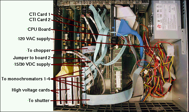 |
| Fig. 8. Computer board and cabling inside RSI 4U rackmount |
When replacing the computer, three 120VAC leads (hot, ground, neutral) must be connected to the inside of the new PC's power supply. This connection should be downstream of the PC power supply switch. This 120 volt supply connects through a diamond-shaped Molex connector to a small Spex power supply, which needs to be saved from the old computer and mounted inside the new one.
The power supply supplies 15 and 30 VDC to the CTI cards and high voltage cards through small white 3-wire connectors (Fig. 9) that plug into the top of each card. The PC should be unplugged before attaching the connectors, because the connector sometimes arcs to the card.
 |
| Fig. 9. Wiring of 15/30V power connector |
BIOS settings
The correct BIOS settings are critical for these ISA cards. If they are set incorrectly, the software will hang with no error messages. DO NOT load "Optimized defaults" or "Fail-safe defaults" in the BIOS. This will make the CTI card appear to be nonfunctional. This is the most difficult aspect of repairing the Spex, because the common defaults do not recognize Spex's cards, and it is very difficult to distinguish between a bad card and an incorrect BIOS setting. In both cases, the software just hangs while displaying the Spex logo.
Turn off everything modern, such as USB, sound, network, mouse, MIDI, etc. in the BIOS. The general rule is to turn everything off (except A20). I suspect it also needs to have 640 kB of RAM. The tricky part is finding the BIOS settings in the PC. Below is a known good BIOS configuration on our RSI rackmount.
| Standard | |
| floppy 3 mode | Disabled |
| video | VGA/EGA |
| halt on | no errs |
| total memory | 523254k |
| Advanced | |
| virus | Disabled |
| cpu cache | Disabled |
| quick size test | On |
| 1st boot | HD0 |
| 2nd boot | Floppy |
| 3rd boot | CDROM |
| other | On |
| skip floppy | Disabled |
| numlock | off |
| A20 | fast |
| typematic | Disabled |
| security | Disabled |
| APIC | Disabled |
| OS | non-OS2 |
| Report no FDD | no |
| EPA | off |
| Advanced chipset | |
| DRAM | by SPD |
| mem freq | DDR333 |
| system bios cache | on |
| video bios cache | on |
| memory hole | on |
| delayed trans | on |
| delay thermal | 16 min |
| on-chip vga | on |
| frame buffer | 1 MB |
| boot display | auto |
| onboard lan | Disabled |
| Integrated peripherals | |
| primary pci ide | on |
| ide 1 master PIO | auto |
| ide 1 slave PIO | auto |
| ide 1 master UDMA | auto |
| ide 1 slave UDMA | auto |
| secondary pci ide | Disabled |
| usb | Disabled |
| AC97 | Disabled |
| init display | pci slot |
| idd hdd block | on |
| power on | button only |
| onboard fdc | on |
| serial 1 | 3F8/IRQ4 |
| serial 2 | 2F8/IRQ3 |
| uart | normal |
| parallel port | 278/IRQ5 |
| parallel port mode | normal |
| pwr non after fail | Disabled |
| midi | Disabled |
| watch dog | Disabled |
| doc | D8000-D9FFF |
| Power management | |
| acpi | Disabled |
| acpi type | s1(POS) |
| pwr mgt | user define |
| video off | blank screen |
| video off suspend | no |
| suspend type | stop grant |
| suspend mode | Disabled |
| hdd power down | Disabled |
| soft off | inst off |
| cpu throttle | 87.5% |
| wake up lan | Disabled |
| pwr on by ring | Disabled |
| resume alarm | Disabled |
| timer events | all Disabled |
| PNP / PCI | |
| PNP OS | no |
| reset config | Disabled |
| resources | manual |
| IRQ | all=Legacy ISA |
| DMA | all=Legacy ISA |
| pci/vga snoop | Disabled |
| assign irq for vga | Disabled |
| Int Pin 1 | 5 |
| Int Pin 2 | 5 |
| Int Pin 3 | 5 |
| Int Pin 4 | 5 |
| Int Pin 5 | 5 |
| Int Pin 6 | 5 |
| Int Pin 7 | 5 |
| Int Pin 8 | 5 |
| PCI Health status | |
| cpu warning temp | Disabled |
| cpu throttle temp | Disabled |
| CPU Voltage control | |
| auto detect | Enabled |
| spread spectrum | Disabled |
Power-up Sequence
- The shutter should make a clicking noise when the PC is first turned on. The shutter should also make a click when the PC is turned off.
- The DM3000 logo is displayed for 20 sec. During this time, the wavelength settings on the monochromators should move as the hardware is initialized.
- After 20 sec, the DM3000 software then checks for error conditions. If no errors are found, it will proceed to the wavelength input screen.
Error Messages
- Simultaneous upper and lower wavelength settings. Check all connections and power cables The heading of this message box indicates which monochromator the software thinks is not responding. All monochromators specified in the hardware.ini file have to be connected and powered up, or this message is displayed, the monochromators will not be initialized, and the wavelength settings will not seek their starting position while the DM3000 logo is displayed.
- Chopper did not respond to set side command. This error message undoubtedly has some meaning, but it is not clear what. If you press Esc, the message box is dismissed and initialization continues normally.
No signal
Even with the lamp off and the shutter closed, there should be a background signal between 200 and 3000 cps, depending on the type of photomultiplier tube used. If there is no background signal, it means no PMT signal is reaching the photon counter.
- By far the most common problem is with bad connectors. Manipulating all the connectors to the PM tubes and signal conditioning modules while the system is running can sometimes identify the bad connector.
- A common problem with old ISA cards is corrosion. Not all early cards used gold-plated contacts. Some used plain brass. We had one ISA board in an HPLC that stopped working until we sanded the contacts with sandpaper.
- The reference signal comes from a PM tube inside the main box. These two reference cables are often overlooked during resassembly because they're underneath the instrument. Some SPEXs use a photodiode instead of a PMT for the reference cell. There is also a power cable underneath the sample compartment next to the blue DB25 shutter cable connector.
- If the PMT is not connected, you will get zero counts for that channel. The PMTs are in ordinary vacuum tube sockets. Sometimes people remove them for safety before moving their Spex. I've also had one fall out during transport. If the PMT loses its vacuum, it will not function.
- If all that fails, it's time to start testing cables and connectors for continuity, cleaning any corrosion or dirt off the cable pins and PMT pins, and then swapping or replacing photomultiplier tubes.
- As an aside, it's a good idea to remove the rhodamine reference cuvet from the sample compartment before transporting the instrument. If it spills, highly fluorescent rhodamine will contaminate the sample compartment.
If the CTI control board controls the shutters and monochromators but there is still no signal, make sure the following are happening:
- The PMT produces pulses when viewed on a scope. The frequency of pulses should depend on the light level. Note that the PMT must be protected from high light levels at all times when it's powered up, or it will burn out. It should never be exposed to more than 10^7 photons/second.
- The DM303 Acquisition Module (discriminator) should be receiving +/−15 VDC.
- The pulse rate of the discriminator output should increase with illumination.
- The chopoff.bin software should find the I/O address of the CTI board at boot-up.
A time-tested way to diagnose whether the problem is software- or hardware-related is to put a portable AM radio next to the CTI card or the computer's CPU. If the circuitry is okay, the sound should change when the PMT is exposed to light. A software problem could be an IRQ not set, some utility (like himem.sys) in the config.sys messing up the memory mapping, or a DMA channel assigned to PCI instead of ISA in the BIOS.
Those ISA cards were actually fairly rugged. Usually, the only thing that ever went bad was the electrolytic capacitors (and, on the CTI cards, the fuses). Both are easy to fix. There are no surface-mount components, BGAs, or hidden layers to worry about. Broken traces on these early boards are also easy to fix. Don't be alarmed if you find some traces on the CTI board that have been cut. Apparently Spex did this on purpose to avoid having to re-design their boards.
Another common problem is the connections between the DA15s and the board. Sometimes those connectors get mechanically stressed, which can cause an open circuit, such as a small crack in the solder joint.
Lamp power supply
The xenon arc lamp in our Spex uses a model ELXE 500-0424 power supply made by Electronic Measurements, Inc. This company is now called TDK-Lambda. According to the data sheet, it provided 41–18 VDC at 12–27 amperes, an ignition voltage of 30 kV, and a boost voltage of 200 VDC. It automatically adjusts the current through the lamp to maintain a constant voltage×current product. A regulated constant-current supply is essential for long lamp life.
The lamp itself is an Osram XBO xenon short arc lamp of either 150 or 450 watts (Spex part no. 1907-OFR)(Osram 69245). These lamps contain pure high-pressure xenon, and goggles and protective clothing should be worn when changing the lamp. The lamp enclosure contains a fan which needs to be kept running for several minutes after turning the lamp off to avoid damaging the housing. Lamps not designated OFR emit UV radiation as short as 185 nm and therefore generate small amounts of ozone.
Miscellaneous
- The photomultipliers use un-cooled Hamamatsu R508 photomultipliers, which are sensitive from 185 to 810 nm. The extra red sensitivity is a trade-off with noise, and we get about 2000 photons/sec compared with 200 photons/sec from a normal photomultiplier. This type of photomultiplier tube is still in use today.
- Spex is now known as Horiba Jobin Yvon.
- An excellent alternative vendor is PTI (Photon Technology International). Update: PTI has now been bought out by Horiba.
- Although the software capabilities of new instruments are vastly improved, basic spectrofluorometer technology has not changed much in 20 years.
Back