Close-ups of mount modifications
 ome readers have requested more detailed images of my modifications to the
CGEM mount. Here they are. Sorry, engineering drawings are not available yet.
There is nothing fancy here. It was a quick and dirty prototype to get
something functional. However, it works extremely well. Once these
modifications were made, drift-aligning the mount became much easier.
The trick is to get the gears adjusted for minimum backlash, but easy
enough to turn so there is some tactile feedback.
Minimizing backlash is especially important between the two 55-tooth gears. If there is backlash, it will be possible to bump the mount accidentally and mess up the polar alignment. So the most critial steps are positioning the outer 55-tooth gear and centering the inner 55-tooth gear.
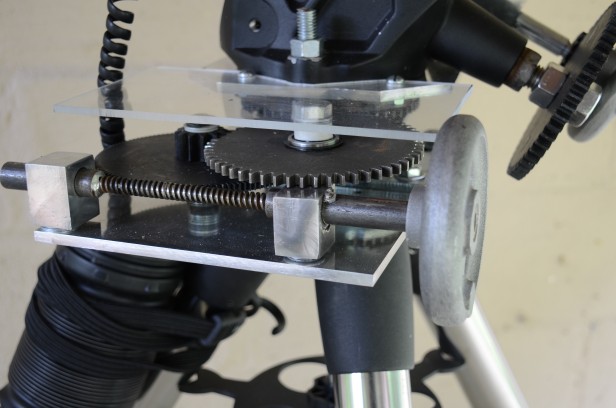
Left side view showing outer 55-tooth gear, 120-tooth gear, and Acme rod
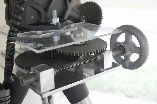
Left side view. The handwheel is press-fitted into the steel rod. The lower part of the turntable, the worm, the 120-tooth gear, and one of the 55-tooth gears are mounted on the large square upper plate. The lower plate (not visible) is attached with flathead screws to the mount and provides convenient attachment points for attaching the gear platform to the tripod. The plastic cover is not just for convenience. Getting a finger caught between these gears in the dark is not fun.
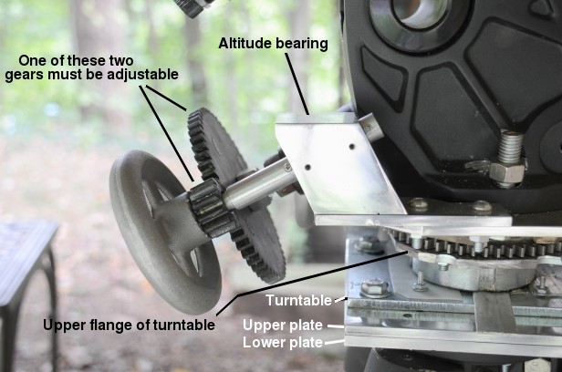
Side view of altitude gears and bearing. The lower flange of the turntable is fixed to the square upper plate. Four 1/4" holes are drilled through the central 55-tooth gear. Above the gear is the wooden spacer, and the octagonal aluminum plate, all of which are fixed to the top turntable flange with flathead screws, so that the mount attachment plate on the top is a flat surface. The altitude adjustment bearing is mounted on this plate, as is the telescope mount itself. Part of the upper flange of the turntable was cut away with an axle grinder to prevent it from blocking the gears on the other side. Note the vertical 1/2" threaded rod which attaches the mount to the octagonal plate.
One of the two altitude adjustment gears must be adjustable because the large gear is fixed to the M18 stainless steel rod and moves in and out slightly as the gear rotates. I made the larger gear adjustable. It's held in place by pressure from two hex nuts. Note that the angle of the altitude gear's axis never changes.
Also note the two small holes in the aluminum block that makes up altitude bearing. There are two set screws in there that can adjust the tension. Don't make these two gears stick out too far, or there won't be enough space to observe through the polar scope. The small metal tab pointing toward the camera is a strip of aluminum that was necessary to stop the turntable from wobbling.
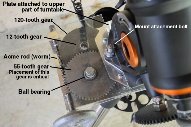
Top view of azimuth gears. The octagonal mount attachment plate is visible. A piece of 1/4" Plexiglas keeps dirt off the gears and acts as a table. The 55-tooth gear is mounted on a ball bearing. It meshes with an identical 55-tooth gear that is fixed to the upper part of the turntable and aligned with the center of rotation the mount.
The orange color in the photo above is a reflection of the sunset, not rust!
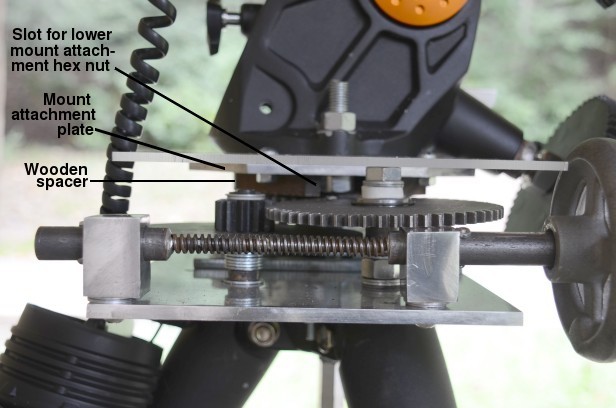
Side view of azimuth gears. A piece of steel tubing has been silver-soldered onto each end of the Acme rod. If you have a lathe, cutting the worm yourself would give a better result. The two aluminum blocks in the foreground are each tapped and held in place by a 1/4"-20 screw. One of the screw holes through the plate is elongated to make it easy to adjust the pressure of the worm.
The wooden spacer has slots in each side. Its purpose is to provide a space for the mount attachment hex nut. The slots need to be big enough to fit a wrench in and tighten the mount securely to the platform. The wooden spacer and octagonal mount attachment plate have a large holes in the center for the protruding part of the mount to fit through. (This actually serves no purpose anymore, and could have been removed instead. This would have made things easier by creating a flat surface on the bottom of the mount.) The spacer and plate are attached to the upper part of the turntable with 1/4-20 machine screws, and the mount is attached to the plate with two 1/2-inch screws.
Since some of these gears are cast iron, they should be painted if the mount is to be left outdoors. The other parts are mostly aluminum or stainless steel.
