Build a solid oak giant binocular mount
 lthough ordinary binoculars are small enough to be used without a mount,
binoculars for astronomical viewing are much larger--sometimes up to two
feet long--and considerably heavier. Unless you have robotic arms, it's
impossible to hold them steady enough by hand to view the stars. Hence the
need for a binocular mount. There are several plans for binocular mounts
on the Internet. Unfortunately, at my location, most of my observing is
straight up, because my house is surrounded by tall trees. To do any
observing, it's necessary to lie down on my back and look up. This means the
binocular mount has to be redesigned to accommodate viewing at the zenith. This
article describes how to build a sturdy, inexpensive mount suitable for viewing
at high angles, capable of holding at least ten pounds with minimal vibration.
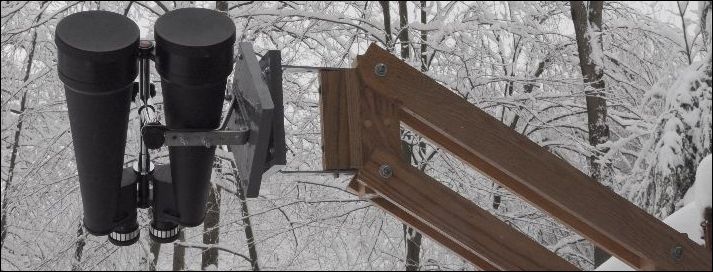
Celestron 25x100 binoculars on parallelogram mount
Why a Parallelogram Mount?
As you recall from high school geometry, opposite sides of a parallelogram are always parallel. This means that in a parallelogram mount, the binoculars (attached to line CD in the figure below) will always be parallel to the central pillar (AB), and they will, hopefully, continue to point at the same object even after being raised or lowered. The lower beam (BD) also helps stabilize the frame, reducing vibrations. In fact, vibrations are the main drawback of the general parallelogram design, and the frame has to be either very large or made of very rigid material like oak to minimize vibrations.
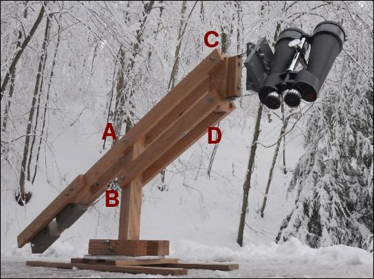
Side view of binocular mount
Most parallelogram binocular mounts are similar in design to the mount shown above. The top beam is extended to accommodate counterweights that balance the structure, which permits the use of low-friction joints. This makes raising and lowering the binoculars nearly effortless.
The vertical wooden piece on the right side (CD) could also extend down several inches to prevent damage to the binoculars in case the weights are suddenly removed (as could happen, for instance, if you have woodpeckers in your area).
Staining Oak with Iron
Oak is the ideal material for a binocular mount, because it's extremely rigid and nearly impervious to insects and rot. However, there's a problem with oak. When oak comes in contact with iron and water, it turns black because of a chemical reaction between iron (III) (abbreviated Fe3+) and tannins in the oak. The tannins in oak are mainly ellagitannins, which are compounds consisting of ellagic acid bound to a sugar molecule. Ellagic acid is easily oxidized by Fe3+, which is an oxidizing agent, to form a black quinone-type compound. Therefore, it's important to give the oak a coating of polyurethane, or it will form an irregular black discoloration as soon as it contacts the snow and mud outside. This discoloration can't be washed off--it can only be removed by sanding or by using chemicals. One way of addressing this problem is to pre-stain the oak by either brushing or soaking it overnight in a solution of ferric chloride. After the wood turns black, soak it in water for a few more hours to remove the excess iron (which is a dark yellow color), dry it, and coat with polyurethane. Ferric chloride is available at electronics vendors like Mouser or Allied Electronics, or you can make your own by inducing steel wool to rust by soaking it in dilute muriatic acid or a weak acid like lemon juice or vinegar.
The photo below shows a piece of oak stained by brushing ferric chloride on it and letting it soak overnight (left), compared to an unstained piece (center). In comparison, a similarly treated piece of pine is almost unaffected (right). The iron turns the wood almost black which, for the oak, is visually appealing. The pine, not so much.
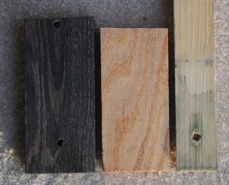
Oak stained black with ferric chloride
Brush it with concentrated ferric chloride solution and spray with water every few hours keep it wet. Don't soak the wood with a dilute solution in a big container, because oak boards are usually made of smaller boards glued together, and they will delaminate. Ferric chloride intended for electronic circuit boards is usually a methanol solution. This must be diluted with water to be effective. Increasing the pH by adding lye or laundry detergent increases the rate of staining. Even though bleach, like iron (III), is also an oxidizing agent, bleach does not turn oak black. If you use lye, wear eye protection and gloves, and mix it in a plastic container, not aluminum, which will dissolve.
An even easier way is to fork over the eleven bucks and buy some Minwax black polyurethane stain.
Parallelogram
The horizontal beams are 6 1/2" apart, measured from center to center, and 21 1/2" long. The central pillar is made of 2 1/2" square oak, 20 1/2" high. The goal is to create a box structure, which minimizes vibrations.
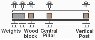
Top view of parallelogram
Attach the central pillar to one side of a 12-inch lazy susan using two 2 1/2" pieces of square oak. Attach the other side to wooden skids or a tripod to provide stability. Skids are more useful than a tripod in snow country. The goal is not to use your binocular mount as a winter skiing event, but to keep it level.
Counterweights vs. Springs
A second design consideration is whether to use counterweights or springs. Using springs reduces both the weight and the overall length by almost half. Springs exert a force that is proportional to their stretched length. However, this is only true over a small distance, so you have to use strong springs, in conjunction with a lever to gain mechanical advantage, so their stretch doesn't exceed their linear range. Two possible positions for the springs are shown in the diagram below. Springs should be used with a turnbuckle to adjust the tension.
The disadvantage of springs is that the overall assembly is no longer balanced, so you need to either attach the central pillar to a fixed object or add feet to prevent it from tipping over. This generally makes springs impractical unless the frame is bolted to something solid or mounted on a heavy base.
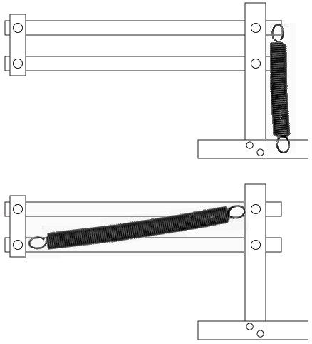
Parallelogram spring orientations
An alternative to springs is to use pulleys and a counterweight-elevator system. This would make it smaller, but more complicated.
Lazy susan bearings and brakes
The ideal way to achieve smooth rotation without stiction is to use a ball bearing lazy susan mechanism. Lazy susan bearings are quite cheap; I bought two 6-inch bearings for a couple bucks at a local Lowes Home Improvement Center. I also had a larger one lying around, which I used for the vertical beam. A lazy susan also provides a large area of contact, which virtually eliminates wobbling around the axis. However, there are two problems with lazy susans.
First, they only work in compression, which means if the joint is not horizontal you need to compress the two rotating pieces together with a loose bolt through the central axis. Otherwise, the stress will pull the two halves of the lazy susan apart, creating friction and noise, and possibly even releasing the ball bearings.
The second problem is that a lazy susan rotates with the slightest touch, which means you have to add a brake to keep your binoculars from turning into a windmill when you get them outdoors. In principle, a piece of rubber or carpet would work, but a metal brake is better because it produces less backlash. In the figure below, I used a simple bent piece of aluminum rotating around a machine screw. An alternative is to wait until dirt gets inside it, which will act as a natural brake.
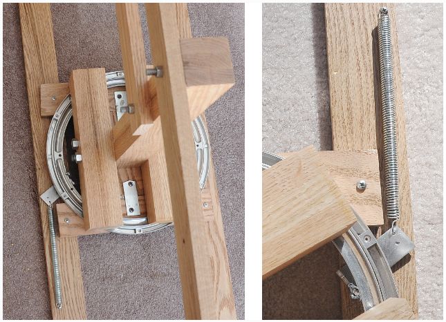
Closeup of lazy susan, central pillar, and brake
The Hinge and Mount
This part requires a lot of precision to ensure that everything is vertical. Although you can buy a steel hinge in most hardware stores, these hinges are not nearly precise enough for our needs.
Center-drill 3/8-inch holes 1 inch deep in both ends of a 1 1/2×1 1/2 inch piece of oak. A drill press is recommended for this step, because the holes must be vertical and precisely aligned with each other. Take two 2-inch 3/8-16 machine screws that have at least 1/2 inch of un-threaded region and screw them tightly in place, leaving the unthreaded region exposed. Cut the screw head off and fix the bolts in place using Loctite. (Screws are available that have a nylon locking patch. These are even better.) These will form the pins on which the assembly will rotate in the horizontal direction.
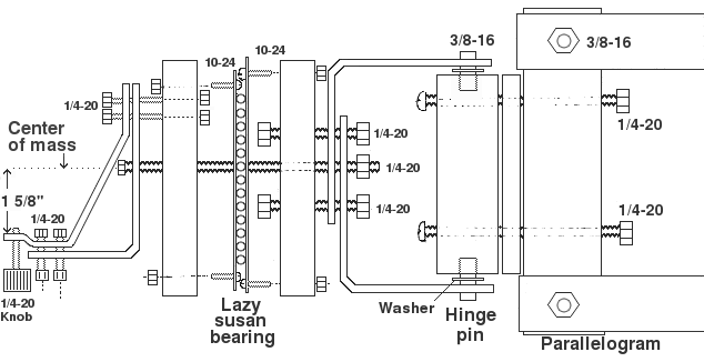
Diagram of hinge assembly.
Insert a 2 1/2 × 3/4 inch wood spacer behind the hinge pin block and fasten it and the hinge pin block to the parallelogram using two 5-inch long 1/4" carriage bolts. The spacer separates the hinge from the parallelogram and makes it easier to rotate the hinge through a larger angle.
Drill 3/8" holes in two 0.165" thick steel 5-inch L-brackets (0.165" thick, 31/32" wide, 5"×5" long) so that they are exactly the same distance from the end. Even better would be to use a single piece of steel bent into a U shape. The pins should fit very tightly in the holes with no detectable wobble. Use a washer on both sides as shown.
Attach the L-brackets to a 6 1/2" × 6 1/2" piece of 3/4" thick wood, which will support the lazy susan, so that the L-brackets are under tension and are squeezing the hinge pin block vertically. (This is a little tricky.)
- Machine screws are used for hinge pins instead of wood screws to maximize the area of contact.
- Add the Loctite after cutting the screw head, not before, otherwise it will melt from the cutting heat.
- The L-brackets available in hardware stores in my area all have pre-drilled holes in weird locations which cause many problems. If you can find L-brackets without holes, use them!
- Make sure the hinge is exactly vertical, or the binoculars will cause it to rotate.
- It might seem that it's easier to assemble this the other way around, by attaching the lazy susan to the parallelogram and putting the lightweight hinge closer to the binocs, but this won't work. The weight on the two sides of the hinge isn't balanced, so the hinge must be vertical or it will rotate by itself.
- The triangular support on the left is made from two 6" L-brackets (0.180" thick, 1 3/32" wide, 6"×6" long). The top one is bent into the desired shape by heating it with a MAPP gas torch until it is red-hot and bending it with pliers (clamp it in a vise first!). This triangle shape is essential in preventing vibrations. Do this in a well-ventilated area if the L-bracket is galvanized.
- The binoculars are attached using the 1/4-20 threaded knob (from McMaster-Carr) on the left.
- The hinge works with the rotating central beam to convert two opposing rotations into one degree of translation (forward/back).
The height of the mounting bracket is critical--the center of mass of the binoculars must pass through the axis of rotation of the lazy susan. Otherwise it'll be unbalanced at some point and will tend to rotate by itself. For the Celestron, this point is 1 5/8" from the center. The mounting post on the binoculars is too short for anything coming in horizontally from the side to reach it, so the L-bracket has to be bent upward so the attachment point is about 1/2 inch higher than the bracket. Simply raising the bracket doesn't work, because the binocular body is in the way.
Vibration
As mentioned above, the biggest problem with parallelogram binocular mounts is their susceptibility to vibration. For small binoculars, vibrations aren't a problem. But 10 or 20 pounds of weight on both sides of a central pivot point creates a lot of angular momentum. You need a very rigid structure to keep something like this from vibrating--a few chunks of square aluminum tubing, or even steel, won't be adequate. Some of the designs on the Internet look like they would vibrate for at least 5 to 10 seconds after being touched. In my location, that's a significant percentage of the time that it's not cloudy.
The need to dampen vibrations dictates both the materials and the design. For example, if you used steel, you'd probably need at least one inch diameter steel pipe (or square tubing) to eliminate vibrations. Then, if you wanted a really stable structure, you'd need to weld the steel pipe to a steel platform to stop it from wobbling. In my first version, I used a large piece of 3/16" × 1½" angle steel for the central post, attached to a 3/8-inch ×12×12 inch base plate. Besides making the mount ridiculously heavy, the steel was susceptible to twisting, which caused vibrations. No amount of bracing was able to eliminate this twisting motion. Even with angle iron as the central pillar and triangular steel braces on two sides, torsion on the horizontal beam caused the central pillar to twist slightly. This caused vibrations that continued for over 12 seconds every time the binoculars were touched.
When I used a 3-inch piece of solid oak for the central column, this source of vibration was virtually eliminated. Vibrations lasted for less than two seconds. That is to say, when you whack the main beam at its most resonant point, (such as by hitting it with your head when you try to stand up), visible movement through the 25×100 binocs was no longer noticeable after 2 seconds. With lighter weight binoculars, vibrations were not detectable at all. There are several design features that account for this.
- Position of the weights. I used concrete bricks instead of iron weights, partly because people always make fun of me whenever I go into a sporting goods store, but also because bricks, unlike weights, can be bolted flat against the central beam. They're also a lot cheaper. It's easy to drill holes in bricks with a carbide tip (hint: use lots of water). If you bolt the bricks to the beam, they increase its rigidity, preventing vibrations. Don't use lead weights--lead is almost impossible to get rid of these days.
- Spacing of the weights. Secondly, the weights are spaced out. This is very effective in damping out any vibrations. If the counterweights were all at the end of the beam, the two ends of the beam (binoculars and weights) would form a resonant structure, and you would have wagging--a low-frequency vibration that takes a long time to decay. The more the two sides differ in their angular momentum, the more inefficiently they will couple, which means vibrations will be damped out faster.
- Steel triangle at point of attachment of binoculars. Even though the steel is 3/16" thick, a single L-bracket will vibrate in a bending motion due to the weight of the binoculars. These vibrations will be transmitted into the wood and bounce back and forth for several seconds, creating high-frequency vibration. The triangle prevents this.
- Large central pillar - prevents twisting of the beam around the central axis.
- Double beams supported at three points. The two oak beams on the parallelogram aren't there to make it look nice. They create a box-like structure that strongly resists bending mode vibrations. The same principle holds true for the hinge.
The weights should be on the upper beam, not the lower beam, to give greater freedom of movement. Even though putting them on the lower beam lowers the center of gravity, they would be more likely to strike the ground when the binoculars are raised.
Degrees of Freedom
The mount has four degrees of freedom: two translations (up/down and forward/back) and rotations for altitude and azimuth (or if you prefer, pitch and yaw). Two rotations around the same axis provide the second dimension of translation (forward/back). A third rotational degree of freedom (roll) is provided by the rotating center post of the binoculars; however, the shape of the binoculars restricts it to ±45°.
Materials
Essential supplies
| Item | Quantity | Cost, US$ |
|---|---|---|
| Oak, 2 1/2" × 2 1/2", 24 inches | 2 | 32.00 |
| Oak, 2 1/2" × 3/4", 24 feet | 1 | 44.00 |
| Oak, 1 1/2" × 1 1/2", 1 foot | 1 | 6.00 |
| L-brackets, 5" | 2 | 3.66 |
| L-brackets, 6" | 2 | 4.74 |
| Loctite | 1 | 5.98 |
| Lazy Susan, 6", square | 1 | 4.48 |
| Lazy Susan, 12", ring-style | 1 | 31.59 |
| Spring, 5 inch, 0.054" wire | 1 | 1.74 |
| Threaded rod | 1 | 5.78 |
| Fast-drying Polyurethane | 1/2 pint | 5.87 |
| Knob | 1 | 3.10 |
| Screws, washers, etc | 10.00 | |
| Concrete pavers | 2 | 0.98 |
| Total | 159.92 |
You can save a few bucks by using a cheaper 12-inch lazy susan and substituting some other type of wood for oak.
Extra supplies needed for making observations
| Item | Quantity | Cost, US$ |
|---|---|---|
| Cheezy Poofs | 1 bag | 7.69 |
| Beer | 12 | 9.99 |
| Total | 17.68 |
You can save a few bucks here by substituting pretzels for the Cheezy Poofs.
Improvements
One problem with the above design is that it's a lot clumsier than holding the binoculars in your hands. To look in a different direction, you have to rotate the apparatus around at least two different axes. The reason for this is that the binoculars are rotating around their center of mass instead of your eye. It makes the design easier, but it can feel a little unnatural.
To improve this design, we need to move the center of rotation to the center of the observer's head instead of the center of mass of the binoculars. This way, the binoculars will move more naturally, the same way as hand-held binoculars, instead of having to rotate around two or more axes simultaneously. However, adapting the current counterbalanced design to this concept is tricky. It would require using weights to balance each axis. We would have weights counterbalancing other weights, which would make the mount impractically heavy. We would also need even stronger beams to accommodate the extra weights, which would make it even heavier. So instead of counterweights, we have to use constant-force springs, which exert a constant force regardless of the displacement.
Feel free to take that idea and build one!
How to thread large-diameter steel rod
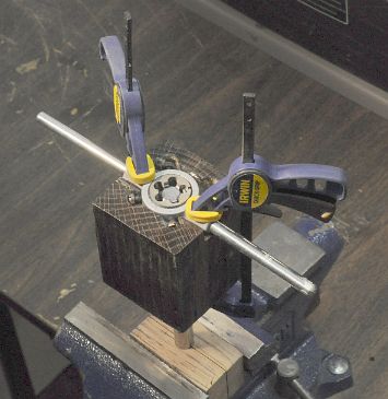
Threading a steel rod
Threading small diameter rod is easy, but larger diameters are a bit tricky because the die tends to either chew up the end of the rod or cut crooked. I couldn't find the procedure for doing this on the Internet, so I will describe it here. Of course, experienced machinists usually just do this with their teeth.
- Drill a hole in piece of 2x2x2 oak. Cut it in half through the hole longitudinally and clamp the rod in a vise between the two halves. This prevents the vise from chonking up the rod while you're threading it. Use the hardest wood available, because considerable clamping force is required to prevent the rod from rotating. Copper soft jaws would also work, but they would eventually get dented.
- Drill a guide hole the same size as the rod through a 3×3×4 inch piece of wood. Drill or mill a notch the same shape as the die wrench as shown. Clamp the die and die wrench to the guide so that the wide side of the die is on the bottom and the die is perfectly flat and centered above the guide hole.
- (Optional) Bevel the first 1-2 mm of the steel rod in a grinder.
- Insert the guide and die over the rod. Spray some Tap Magic and turn clockwise 10-15 degrees, then counterclockwise to remove the chips. This will take a fair amount of pressure. Repeat until the threads are the length of a nut, or until you are exhausted, whichever comes first.
- After cutting the thread, tighten a nut on the rod a few times to smooth out the threads and remove any excess chips.
