Introduction
 n Part 1 I gave an overview of the design of our high-resolution spectrograph. In
this section I describe the construction details. The general idea here is to build
each section independently in such a way that it can be attached to a solid
aluminum plate with a single screw. Since this instrument will be used outdoors,
all the parts are either stainless steel, plastic, or aluminum. As described in
Part 1, the design used here eliminates field
curvature, spherical aberration, and astigmatism. The spectral image is sharp
across the width of the focal plane.
Parabolic mirrors
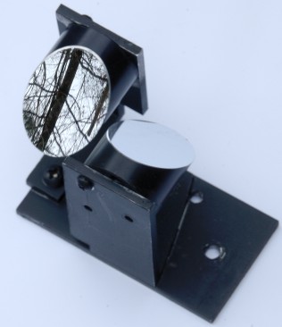 Parabolic mirror arrangement
The spectrograph uses two 1-inch diameter off-axis parabolic mirrors (Thorlabs MPD254508-90-F01). Parabolic mirrors create an image that is offset by a fixed angle, in this case 90°, from the incoming ray. For reasons discussed in Part 1, the grating is not in the same plane as the mirrors, but is suspended vertically above them. The incoming light rays are reflected by the collimating mirror up toward the grating, then back to the camera mirror. Collimation is achieved by positioning the mirror exactly one focal length from the slit.
The figure at right shows that the two mirrors also point in opposite directions. This is the biggest advantage of the 90° mirrors. It allows the incoming and outgoing beams to be parallel, and eliminates the need for extra flat mirrors. Since the mirrors I used had a focal length of only 100 mm, those flat mirrors would have made it impossible to bring a camera close enough to focus.
If you pay careful attention to the geometry, the entire spectrograph can be made without any other optical elements. If your camera is too big to reach focus, a −200 mm focal length concave lens can be added to increase the available distance (in this case, doubling it). If I built one of these again, I would use 150 mm focal length mirrors to make focusing easier. Longer focal length mirrors also tend to have less optical distortion. The disadvantage is a larger spectrum image and hence lower sensitivity, as the faintest bands will tend to get lost in the camera noise.
Make both mirror mounts from the same piece of ⅛" aluminum angle so they are exactly the same height and orientation. Then attach them to a flat piece with single screws so you can adjust their relative angle before tightening them down.
It's critical to cant the parabolic mirrors inward so they focus at exactly the same point on the grating. The grating also has to be perfectly straight, centered, and level, or the spectrum will be curved. In the original 2007 paper (Applied Optics 46, 3095), Schieffer described a procedure using a laser to adjust the mirrors. Adjustment can also be done manually if you mount the mirrors such they can be rotated by hand. Rotate the first mirror so that the reflection of the slit is at the center of the grating. Make sure the image of the slit is perpendicular to the lines in the grating. It must illuminate as much of the grating as possible, because resolution is directly proportional to the number of lines in the grating that the beam hits. Then rotate the second mirror until the image of the spectrum is straight.
The mirrors must have the same focal length and must be arranged precisely symmetrically; otherwise, the spectrum will not be horizontal. If the mirrors and grating are not sufficiently well aligned, the spectrum will be in the shape of an arc.
Condensing lens
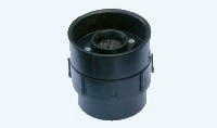 Condensing lens
I mounted a 100-mm focal length, 24.5 mm diameter fused silica lens in front of the slit. Its sole purpose is to concentrate as much light as possible on the slit. For astronomical uses, this lens would be replaced by a telescope. Thus, the main feature of this lens is that it's easy to remove. It's there mainly for testing purposes. The lens is in an aluminum mounting flange attached to two threaded ABS fittings, which allows a small amount of focusing. You might recognize the ABS parts from the plumbing department of your hardware store.
Slit
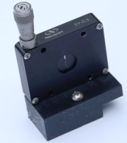 Slit
Slit
I mounted the slit (a Newport SV0.5) 101 mm from the collimating lens. The slit position is critical. Even a 1 mm difference in distance between the slit and the mirror is enough to make the spectral lines blurry. If the slit is out of focus, the spectral lines will also appear bent into a C shape. The lines bend in opposite directions depending on whether the slit is too close or too far away, so the direction of bending is a good test of whether the slit is in focus.
When taking spectra of nearby images, such as a lamp, it's often necessary to add a second slit to prevent optical distortion. As with most other spectrograph designs, measuring nearby objects often produces massive amounts of coma which makes the image appear fuzzy. This can be suppressed by use of a second slit.
The slit is the most expensive component here, so it would be the first candidate to make by hand if you want to cut costs. It's easy to make a series of fixed interchangeable slits from pairs of single-edge razor blades, and they work just as well. The edges must be kept scrupulously clean, or you will get horizontal lines cutting across the spectrum.
Lens
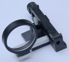 Concave lens
Unfortunately, with the two 100-mm mirrors, it was impossible to mount the camera close enough to reach focus.
In order to get the camera to focus on the slit, it was necessary to add a lens between the slit and the collimating lens. I mounted a UV Plano-Concave 50.8mm Dia. × −250 FL, uncoated fused silica lens (Edmund #08-074) on an adjustable platform made from an old Celestron camera adapter (Item # 93626). This adapter was far too flimsy to support a DSLR, but after being cut apart and modified to improve its precision, it found a use here. The adjustable lens also makes the slit position less critical.
These babies were on sale, and were really cheap.
Grating
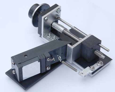 Grating adjustment mechanism
The grating was a 25.4×25.4 mm, 600/mm ruled grating, 500 nm blaze (Thorlabs GR25-0605).
As mentioned in Part 1, it's worth spending some effort to build a precision mechanism for rotating the grating. The picture above shows one possibility. I mounted the grating on a 1-inch-wide piece of black Delrin (aka polyoxymethylene or acetal, McMaster 8575K146), which rotates around an axis that is as close as possible to the center of the grating.
A ¼-20 leadscrew was attached to a partially threaded ¼-inch diameter stainless steel rod, and thence to the tuning knob, using a threaded coupler. The rod was press-fitted inside a ball bearing (not visible). The bearing is then pressed tightly into a square piece of Delrin with a round hole drilled into it. This is visible in the photo just under the tuning knob. A small amount of black cyanoacrylate glue (Loctite Black Max) helps hold it in place, but it's really impossible to glue anything to Delrin and the fit must be very tight. If you can't get it tight enough, you may need to mill out a disk-shaped cavity and hold the bearing in place by squeezing it in a sandwich (visible in the second photo from the bottom, below, under the brass-colored timing pulley).
The moving platform was made from another 1-inch thick piece of black Delrin, and was tapped with ¼-20 threads. A small piece of aluminum with a pointed edge was bolted to the platform. As the leadscrew rotates, the platform moves up and down, lifting the edge of the Delrin and causing the grating to rotate. A second, smaller (⅛-inch) fixed rod parallel to the leadscrew helps guide the platform.
Normally, you'd attach the bottom ends of the leadscrew and guide rod to something, but I decided to leave them floating, and put a thin piece of black ABS sheet (McMaster-Carr) underneath instead. This sheet is gently curved, which causes it to act as a spring. Along with the guide rod, this keeps the moving platform from rotating, and evens out any imperfections in the leadscrew. The result is an incredibly smooth rotating motion.
Precision is also increased by using a large diameter (¼") for all the rotating parts, and by using big chunks of Delrin for the platform and grating mount. The larger the contact length of the leadscrew with the platform, the more accurate it will be.
The grating is held in place by two pieces of ABS held in place by screws, as shown on the left of the picture above. The grating is squashed between two pieces of adhesive-backed rubber, and can be removed by loosening the two screws on the far left. The adhesive-backed rubber doesn't stick to Delrin very well, so you may need to add some contact cement to hold them in place. The grating mechanism is mounted vertically, with the knob pointing up.
The picture above shows an old, beat-up grating mounted for the purposes of taking the photograph. Keep your real grating in its box until you're ready to make measurements, and avoid getting fingerprints and dirt on it at all costs. Once a fingerprint gets on your grating, it cannot be removed, even with organic solvents.
It's probably worth mentioning that professional astronomers usually use fixed gratings, so none of this is really necessary. However, using a fixed grating makes it more difficult to record spectra in the infrared and UV.
Mirrors
The flat mirror shown in Part 1 was not needed, since we are using a Gil-Simon configuration. The advantage of 90° offset mirrors is that the camera faces the light source, which makes balancing the spectrograph on a telescope much easier.
Camera mount
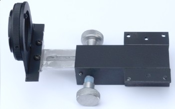 Camera mount and focusing mechanism
The camera mount is similar to the one I used for building an ultraviolet camera lens. Cut long slot in a 1 × ¼-inch aluminum flat into a U shape, like a tuning fork, and epoxy a rack gear into the slot. Press-fit a matching gear onto a stainless steel rod, and mount it crosswise in a 1-inch (i.d., ⅛" wall ) square aluminum tube (do the mounting step first). The aluminum flat should be polished, not painted. It slides against the inside top of the square tube, with the gear teeth pointing down. Small strips of Delrin or Teflon inside the tube are needed keep the rack from wobbling.
A Fotodiox F-mount adapter (07LATMNK or 07TMNKFC) is bolted to an aluminum angle cut into a U shape as shown, using three 2-56 thread screws. This is then attached to the base of the “tuning fork”, using aluminum spacers if necessary to get the correct height. This particular adapter is designed for Nikon cameras with an F-mount, but adapters for other cameras are also available.
The entire assembly is mounted underneath the main plate of the spectrograph using the six screw holes shown, using short 8-32 machine screws. This prevents it from interfering with the optics.
Painting
Aluminum parts were lightly sanded, then cleaned with acetone and sprayed with self-etching primer. They were then sprayed with Rustoleum Flat Black Protective Enamel and then cured overnight under a 15-watt mercury germicidal lamp.
Modifications
An important factor that I overlooked is vibration. At high resolution, even a slight bump is enough to move the spectrum by one pixel, which causes severe blurring. The components must also be solidly attached. I will eventually replace the ⅛-inch-thick aluminum plate with ¼-inch for increased rigidity.
I also attached a timing belt (MXL,⅛" wide, McMaster 1679K87) and two MXL timing-belt pulleys (0.080" pitch, pitch diam. 0.255 and 1.528 inches, McMaster 1375K11 and 1375K53) to the leadscrew. The belt goes to a mechanical counter (McMaster 1697T65) so the position of the grating can be precisely known. This increases the speed of the counter by 6×. The counter eliminates the need to take a reference spectra every time the grating is moved. An alternative would be to use a ten-turn potentiometer and an ohmmeter. This is not really cheaper, as you would also need a 4½ to 6-digit panel-mount ohmmeter like this one, this one, or one of these.
The spring should really be on the platform, not fixed as shown in the picture above. I also flipped the L-bracket on the camera mount around (left of photo above) to gain an extra 10 mm of backfocus.
Putting everything together
Position the components with masking tape to make sure it all works before fixing them in place. Then tap some 8-32 holes in a ¼ or ⅛-inch aluminum plate and attach the components using short screws. Tapping a hole takes more time, but makes construction much easier, since you can remove the component easily and mount it somewhere else. It also makes it possible to mount the camera focusing mechanism on the underside of the plate, using similar short screws, without interfering with the optics.
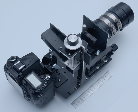 Spectrograph with basic components installed. Ruler is 150 mm long. The
concave lens is not visible in this photo.
With the aluminum cover attached, the final size was 5.5W × 7D × 9"H and the final weight was 5.5 pounds.
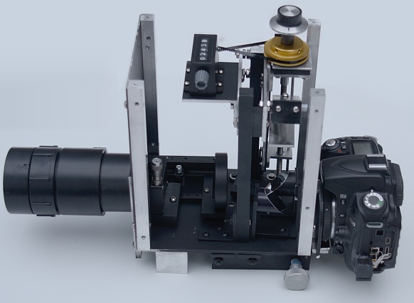 Final spectrograph after installation of counter. Side, back, and top panels
removed.
A 5-digit mechanical counter was attached using miniature timing belts. One rotation of the knob changes the reading by about 60 units.
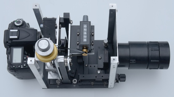 Top right view. Despite appearances the timing pulleys are not made of solid
gold, which would have made them slightly more expensive.
