
Inexpensive Incubator Alarm System using Linux
Overview
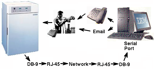
This is the setup of our incubator alarm system. The incubator
has a serial port on the back that sends out readings of the
temperature, carbon dioxide concentration, and humidity at regular
intervals. The RS-232 signal goes through our network wiring to a
patch panel. A Linux server with a multiport serial card monitors
all the incubators simultaneously. The messages from the incubator
look like this:
37.0 deg C 5.0 % CO2 81 % RH |
37.0 deg C 3.0 % CO2 LO 81 % RH |
Note that only the network wiring, not the network hardware, is used for the signals from the incubator. The RS232 signals never touch the computer network signals. It's a good idea to use a dedicated color for all cables carrying serial signals. We could also have used the telephone wiring system, since in our building the same type of wire is used for the telephones and network connections. But then we would have gotten in trouble with the Phone Cops.
Serial to RJ-45 adapters
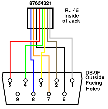
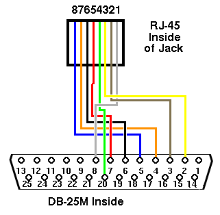
We use a DE9F to RJ45 adapter, part no. 01910 from www.pccables.com to get the serial signal from the incubator to the network wall jack. The first figure above shows the wiring viewed from the back (inside) of the RJ-45 jack on the adapter and the front (outside) of the DE9F. The wiring is not critical, but it's obviously important to be consistent because once the adapter is assembled, the wires are no longer visible. Note that the color of the wires in this adapter is unconventional. If your incubator used a DB25 serial connector instead, it would be wired as shown on the second figure. An identical adaptor is used in the wire closet to convert the RJ45 back to a DE9, which is then plugged into a serial port on the server.
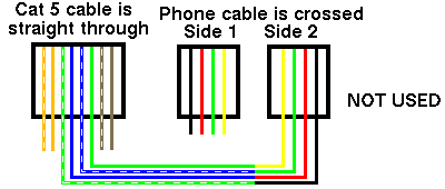
For the telephone, a different type of adapter can be made by splicing the appropriate lines of a Cat-5 patch cable to a telephone cable. Note that in a phone cable, the two ends are inverted, while network patch cables are wired 'straight through'. When making the adapter, pay attention to the positions on the plug, not the colors of the wires. This figure shows the positions as viewed from above the clear side or "top" of the plug:
In fact, this second adapter is not necessary. Just run a phone cable
from the computer's modem to the phone jack. Unfortunately, after
we set up our modem, we discovered that we didn't actually have any
phone jacks in the wire closet. But there were lots of phone wires.
So we purchased a little box that has a RJ12 surface-mount jack
with a 110 punchdown block inside and connected it to the fax
line. The box is wired up as shown below, viewing the RJ45 from the
front (outside).
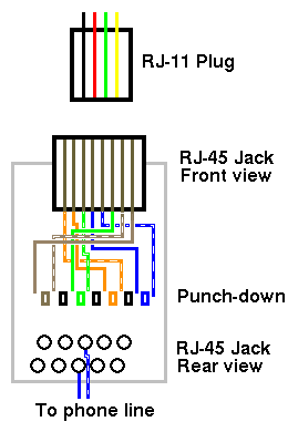
A punch-down block consists of little metal contacts on either side of color-coded plastic dividers. Traditionally, the solid color wire is always punched down on one side and the striped color wire on the other. Be sure you use the correct punch-down tool. There are two types: 66 and 110. If you use the wrong type, you will break the plastic divider.
Only two wires are needed to connect to a phone line. These correspond to the center two lines (green and red) in the RJ-11 plug and the blue and blue/white wires (the center pair) in the patch cable. The two lines go to the appropriate location on the 110 punch down block used by the phone system. The voltage across the phone line should be 47 volts DC. It goes without saying that you must be very careful not to accidentally connect the phone line to your router or any other network equipment.
TIA/EIA-568A and 568B wiring color codes
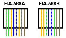
Category 5 cables are wired in either EIA-568A or EIA-568B patterns. The figure above shows 568A and B color coding as viewed from the clear side (the "top") of the RJ-45 plug. These configurations give better performance than other arrangements. Obviously, both ends of the cable must be wired identically. Even though 568A and 568B patch cables can be used interchangeably, it's best to standardize on one or the other. Ideally, this fact should be documented somewhere.
Just for the record, we use EIA-568B at this location.
Important: The computer and freezer should be protected from electrostatic discharge by placing an RS-232 optical isolator or a diode-based surge protector such as a Tripp-Lite DRS232 between them. Otherwise, a surge could destroy the serial port on the computer or the freezer.
How to make a category 5 patch cable
When making a Category 5 network cable, it's important to minimize the untwisting of the twisted pairs. This is not important for serial cables, but for network cables, untwisting causes loss of bandwidth, making your network connections slower.
- Cut the desired length of Category 5e or higher cable.
- Remove 1 inch of the outer insulation from the cable jacket.
- Line up the individual wires as shown for 568A or B and untwist them to about 1/2 inch from the end. If the colored pairs are stuck together, carefully cut them apart with a razor blade. Do not de-insulate the wires. If any of the wires get nicked, start over. Trim the end with a pair of scissors so the ends of the wires are even.
- Insert the wires into a blank RJ-45 plug and crimp the plug with a plug crimper.
- Test the cable with a Category 5 cable tester. Cable testers have separate remote and local units so that cables of any length can be tested.
Incubator Monitoring Software
The include file is incubator.h.
The alarm program is incubator.cc.
Note the following points about the program:
- The serial ports are multiplexed using the select() statement, which blocks waiting for input.
- In open_port(), the serial port is set to canonical I/O.
- The program tries to find the port address automatically. If it can't, the address is assumed to be 0xC800, which is the address of the RocketPort serial port (ttyR0 to ttyR7). See linuxsetup67.html for details on setting up the RocketPort in Linux.
- The program spends most of its time in monitor(), waiting on the select() statement. This keeps the system load at 1.0, but in fact there is actually very little load on the processor.
- When input comes in on one of the serial ports, the program figures out which serial port sent a signal and then jumps to handle_input() where it figures out what to do next.
- The first 29 bytes of the incubator string contain the date and time, which are often (or should I say "always") set incorrectly on incubators, so they are stripped from the string and replaced with the computer's date and time. Trailing junk is also stripped.
- Every time input comes in, it is appended to a log file and the external command "logcommands" is executed, which copies the log file to the http directory. The program also creates a small web page with a META command that causes the user's browser to automatically refresh every 40 seconds. This way, the user can leave a browser window open and monitor what is happening to the incubator continuously. (This is fun for some people.)
- If an alarm state is reached, the program executes the appropriate command from the alarm-commands file, which is shown below.
- The software should be run as its own user, e.g. "incubator", not as root. This may mean setting the device node to 777 or changing its ownership. Set the incubator's name to "The Incubator" in /etc/passwd so recipients of emails know they're coming from the computer.
Auxiliary files
- logcommands does whatever extra processing is needed
when data is received. It must be made executable.
#!/bin/bash
# logcommands - Commands
  to be executed by alarm
# after each temperature
  measurement.
# Use alarm-commands to
  add commands in case of
  temp alarm.
cp ./incubator.txt
  /usr/local/httpd/htdocs/
- The locations file gives a descriptive list of what is on
each serial port. It's needed for the freezer alarm but mostly ignored
for the incubator alarm.
# Locations for conifer
# Syntax is:
#  port (0,1,2,etc)
  <tab> Text string
# For DGH module,
  up to 4 freezers per
  port.
0       Incubator 0 ttyR1
1       Incubator 1 ttyR3
- The alarm-commands file is a list like the one shown below.
This example shows two incubators, 0 and 1. If no commands are
found for a given incubator, the incubator is ignored. We have
three columns to make the syntax compatible with our freezer
alarm software. For incubators, the second column is ignored.
The program automatically sends a message to syslog, so it is
not needed here.
# alarm-commands file
# Any commands here will
  be executed when alarm
  rings.
# Format is:   Incubator
  Threshold  Command
# 2nd arg is ignored but
  needed for compatibility
  with freezer software
#Incubator no.  Command
#incubator 0
0    0   /bin/mail jrip
  per@burpelson.afb.mil <\
         /home/incubato
        r/incubator-current.txt
0    0   ./alarmdial
1    1   /bin/mail jrippe
     r@burpelson.afb.mil < \
         /home/incubator
         /incubator-current.txt
1    1   ./alarmdial
(Note that these commands must be on a single line. They are wrapped here because one browser (from a large company whose name starts with 'M') doesn't render the page properly if the text is too wide.)
- alarmdial is another text file that dials the modem, waits
for an answer, and then hangs up. It must be made executable.
# alarmdial file
 /usr/sbin/pppd connect
  '/usr/sbin/chat -V "" ATM0 \
 "" ATDT9,13015551212 CONNECT'
Note that we have to dial a '9' to get an outside line. In order for alarmdial to work, the linux kernel must be configured for ppp.CONFIG_PPP=y CONFIG_PPP_ASYNC=y
- /etc/ppp/options must be set up to "noauth", which
prevents pppd from requiring a password, and "maxfail 1",
which prevents it from trying to redial when the modem gets
a "NO CARRIER" signal.
# /etc/ppp/options
/dev/ttyR7
57600
defaultroute
noipdefault
crtscts
noccp
nodetach
noauth
maxfail 1
idle 20
novj
I originally tried a program called "wvdial" for this purpose, but it proved impossible to get wvdial to stop redialing when the carrier was dropped by the recipient. A new version of wvdial appears to have this capability, but it proved to be impossible to get it to run for some unknown reason.
- Set up the file /etc/ppp/chap-secrets to a dummy password
to cover the unlikely possibility that someone is running
a ppp server on their cell phone.
# /etc/ppp/chap-secrets
#hostname       *       password
fsdfsfs         *       fsfsf33sfs
- The incubator.html file uses one frame (incubators-left.html)
for contact information and one frame (incubator.txt) for the incubator
readings. (Sorry for the wraparound)
<HTML> <HEAD> <TITLE>Incubator Logs</TITLE> </HEAD> <!-- Could be <FRA MESET cols="90%,10%"> --> <FRAMESET cols="25%,7 5%"> <FRAME src="in cubators-left.html"> <FRAME src="ht tp://burpleson.af b.mil/incubator.t xt" frameborder="1"> </FRAMESET> <NOFRAMES> <A HREF="incubator. txt> Incubators</A> </NOFRAMES> <HR> </HTML> - serial.h is also needed to get incubator.cc to compile. If you don't have this, a serial.h appropriate for your system is in the linux kernel source.
Back