
Homemade heated telescope dew shield - design and plans

The finished dew shield looks a lot like an aluminum wastebasket, but it is much lighter, because the insulating layer is mostly air.
 henever the surface temperature of an object falls below the dew point, you
get "dew" or condensation forming on the object. On a telescope, that makes
it look like you're viewing the stars through a thick fog (which, come to
think of it, you are). While it's possible
to eliminate dew with a hair dryer or by throwing a heating blanket over the
telescope, the best solution is a dew shield with a low-power electrical
heater that keeps it continuously warm without producing waves of heated air.
henever the surface temperature of an object falls below the dew point, you
get "dew" or condensation forming on the object. On a telescope, that makes
it look like you're viewing the stars through a thick fog (which, come to
think of it, you are). While it's possible
to eliminate dew with a hair dryer or by throwing a heating blanket over the
telescope, the best solution is a dew shield with a low-power electrical
heater that keeps it continuously warm without producing waves of heated air.
Most commercial dew shields are made of acrylonitrile butadiene styrene (ABS) copolymer, which is a type of plastic that is thermally insulating, nonreflective, and most importantly, lightweight. However, the shields and the heating elements needed to make them work are fairly expensive, and quite often unavailable because the vendors are out of stock. So it has become a standard practice for amateur astronomers to build their own.
Some people have made dew shields from sonotubes, which are 8, 10, or 12-inch diameter cardboard cylinders used for pouring concrete pillars. These are fairly rigid and thermally insulating. In fact, it is easy to cut them longitudinally and glue the sides together with carpenter's glue to make any diameter, or even bend them into a conic section.
Oner problem with sonotubes is that you have to buy them in 12-foot lengths. In my area, there are no hardware stores that sell them--the only option is a cement company staffed by tough-looking guys with bumper stickers on their pickups that say things like, "Concrete workers keep it hard." I suspect those guys might be skeptical if I told them I was building a highway overpass. On the other hand, if you are planning to build a pier for your telescope, or for that matter, a highway overpass, you will need a sonotube anyway, in which case that might be a good solution.
But there are two more disadvantages of sonotubes: one, they get moldy and deteriorate when exposed to water, and two, they're really heavy. A 12-inch sonotube weighs about 3 pounds per linear foot. Painted black, at midnight, it might even be dangerous. How embarrassing would it be to have somebody write on your tombstone, "Died after being hit on the head by a piece of cardboard" ? Very. But cardboard is cheap, easy to work with, and it's a good insulator for heat.
Another lightweight material, aluminum, is a poor insulator, but it reflects heat very efficiently. In fact, it's one of the best reflectors of infrared radiation available, right after gold, copper, and silver. Aluminum is also a good conductor of heat (about half as good as silver, and twice as good as brass). This would be a problem if you used solid aluminum: most of your heat energy would be simply conducted to the outside of your shield and lost. To make aluminum work, you need two layers of aluminum with an insulating barrier between them. Well, as Strother Martin might have said, that's what what we've got here is one of.
Construction
To make an aluminum dew shield, we will use two layers of 14" aluminum flashing and one layer of Reflectix, which is aluminized polyethylene plastic material covering a core of bubble wrap. Reflectix is not rigid or durable enough to use by itself (although this guy and this guy have tried it, with good results), but when encased between two layers of aluminum flashing, you get a strong, water-resistant structure that almost completely blocks the transfer of heat.
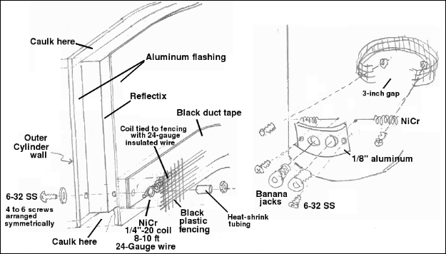
Cut a length of aluminum flashing about four inches longer than twice of the desired circumference of your cylinder. Cut a piece of Reflectix to exactly one circumference in length, and make its width 1 inch less than the width of the flashing. Line up one end of the Reflectix with the flashing and tape them together with duct tape as shown, centering it so that there is a 1/2 inch gap on either side.
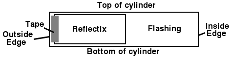
Roll up the cylinder to the desired diameter, keeping the layers as tight as possible, until there are three layers such that a single layer of Reflectix is squeezed between two sheets of aluminum. Stick a small piece of tape to hold it in place, then tape the outer end of the flashing using aluminum flashing tape. Be sure to use aluminum flashing tape, not duct tape, which would get dirty and deteriorate after getting wet. The flashing should overlap a few inches, but the Reflectix must not overlap, because this would give an uneven shape. Avoid the temptation to fold back extra flashing tape over the ends of the tube--that would mess up the later steps.
Drill holes near the top and bottom of the cylinder at the point where the flashing overlaps itself and fix the diameter by screwing 1/2 inch 6-32 stainless steel screws through all three layers. The screws can be tightened to help squash out a small amount of overlap of the Reflectix. Fix the nut in place with Loctite. Using stainless steel is critical: the shield will be exposed to water, and zinc-coated screws will eventually rust.
Use a heat gun or razor blade to remove any extra Reflectix, so there is a 1/4 to 1/2 inch depression at both ends. Fill this depression with caulk. I happened to have aluminum-colored caulk, but obviously any color would work. This will seal the ends so water can't get between the layers. It also makes it a little more rigid. Use ethyl alcohol to clean off any extra caulk or smudges. Do not use any type of rigid cement or glue--the flashing will flex and crack it.
Mask the bottom 3 1/2 inches and spray-paint the inside with flat black paint. The ideal paint is a new type of flat black called Krylon "ultra-flat" camouflage paint (4290), which is supposedly less reflective than regular flat black. Do not paint the outside. The aluminum color will actually assist in retaining heat. The bottom two inches, which will contact the telescope, should be free of paint.
Bend a 1/8" × 4" × 1" aluminum flat to match the curvature of the cylinder. Mount two banana jacks in the center, over top of corresponding holes as shown in the figure above, and fasten it to the outside of the cylinder with two 1 1/2 inch stainless steel 6-32 screws about 3 inches from the bottom. This step is necessary because the cylinder is too thick and not rigid enough for the banana plugs to be mounted on it directly.
Heating element
The most convenient material for a low-power heater would be some kind of flat electrical conductor with a resistivity about 6 ohms per foot. Anything conductive that can handle the power without burning up will work. One material I tried was the extra scraps of Reflectix left over from making the shell. The outer layers of Reflectix are aluminized polyethylene. The aluminum conducts electricity, but it's covered by a thin coating of plastic. In order for it to carry current, you have to remove the coating by gently wiping it with acetone. In my tests, a 2 foot x 1 cm piece of Reflectix pulled 0.2 amps from a 6-volt battery. The temperature of the Reflectix rose from 73.4° to 78.5° in 7 minutes. With 12 volts, the temperature rose from 70.6° to 91.4° before the connection broke. So aluminized polyethylene works, but it doesn't seem to be reliable enough to use as a heater.
The standard material for a heating element is nichrome. This is what we use in the lab on our gas chromatograph. Nichrome can be heated red-hot in air without oxidizing. When we put 60 volts through it, it raises the temperature to 500° F without discoloring. Normally nichrome is tack-welded, not soldered, to the electrical contacts, because the high temperature would melt the solder, but for low temperatures soldering is okay.
The optimum length depends on the wattage you need. A shorter coil will use more current and therefore become much hotter, but it will also drain your battery faster and create more air currents. So you need to calculate the resistance first.
First we need to calculate the number of watts needed. A quick engineering
rule of thumb
is
1 kW = CFM × Temperature Rise (°F) / 3000.
As a crude approximation, to raise one cubic foot of air by 30 degrees in one minute
would require 10 watts. In reality, we would have to take into account conduction
through the walls and air convection, which can be calculated knowing the heat
capacity and thermal conductivity of the substrates. If there is condensation
already present, we have to include a term for the start-up watts, taking into
account the latent heat of vaporization of water. For radiation, we would use
Planck's law and the Stefan-Boltzmann equation for black body radiation, along
with absorption by the glass and cooling caused by radiation into space. Taken
together, this gives ... umm, er ... about ten watts. (The actual calculations are
left as an exercise for the reader.)
Using Ohm's law (E=IR, P=IE, and P=I2R) and taking into consideration the power capacity of your battery, we can calculate the resistance needed to produce the desired power. Since our maximum temperature is only 100°F, we don't have to worry about things like using ceramic insulators or burning up the wire. The resistivity of nichrome is 110e-6 ohm-cm. Suppose the battery can supply 12 volts at 10 watts for a reasonable period of time. We might pick 9.6 watts, which gives i = 0.8 amperes and R = 15Ω. If the circumference of the shield is 71.8 cm, we can use the formula R = rho × L / A, which gives the resistance of a wire with length L, resistivity rho and cross-sectional area A. We calculate A = 110e-6 × 71.8 / 15 = 0.000526 cm2. From the familiar A=πr2, we now know that the radius needed is 0.0129 cm, diameter=0.0259 cm = 0.0102 in.
Looking at the size table http://www.heatersplus.com/nichrome.htm or http://www.mcmaster.com/#nickel-wire/=988oqj we find the closest size is 30 gauge, which is 0.0100 inches in diameter. If you used a larger wire, you would have to make multiple loops or a helix or zigzag pattern to squish all that wire into the available space.
One vendor sells small quantities of nichrome wire as small as 40 gauge (0.0031 in).
If you use a coil, the most important thing to remember about helical heating elements is that the coil turns must be evenly spaced. Wherever they are bunched up, the temperature will increase much more than other places. The same is true for zigzag patterns, which have bunched-up areas by definition. In the lab, we have had Teflon tubing turn black when this happens. In an electrical appliance, it could start a fire. Of course, it's unlikely that you would start a fire inside your telescope (although it's happened), but uneven heating will cause convection currents.
Installing the Heating Element
Take the appropriate length of nichrome wire (calculated above). If you need to wrap it into a coil, the easiest way is to attach a 1/4" or 3/16" threaded steel rod to a variable-speed electric drill and slowly wrap the wire around the threads. Then unscrew the coil by reversing the drill and holding on to the coil while wearing gloves. Stretch the coil out and attach it to the fishnet-style plastic deer fencing as shown in the diagram above, using small pieces of 20-gauge insulated wire as twist-ties so the coil fits inside your cylinder. If it's not a coil, no fencing is needed, and you can skip this step.
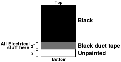
Now we finally get to use more duct tape! We've been waiting so long! Apply two layers of 2-inch-wide black duct tape to the inside of the tube near the bottom, leaving a 2-inch space where it will fit over the scope. Attach the nichrome coil to a flexible grid, such as a piece of plastic deer netting. (Yeah, I live out in the country, where we have tons of this stuff lying around. Just be grateful I didn't specify a cow patty as the heating element.)
Attach the coil and the fencing to the cylinder using plastic or stainless steel screws. If you use stainless steel, insulate them by sliding a piece of plastic tubing or heat-shrink over them, and then attach the nichrome coil to the screws by twisting a piece of 20-gauge insulated copper wire around them. If it's not a coil, just glue or tape the nichrome to the black duct tape on the inside wall. Solder, weld, or crimp the heating wire to the banana plug. Check to make sure the wire is not shorted to the aluminum flashing and that it still has the expected resistance before applying power. If it shorts out, you'll blow the fuse in your Power Tank cable or maybe even start a fire.
It's a good idea to install a thermometer probe inside the cylinder at this point, and to install an LED or an ammeter so you can tell if the heater is working. See here for how to calculate the value of the resistor needed for the LED. All you need for an ammeter is a digital panel meter ($8) and a 0.1Ω or 0.01Ω, 10 watt shunt resistor made from a piece of copper wire. With 10 watts of heat, the compartment should warm up from 50° to 80° within a few minutes.
Controlling the heating element
It's intuitively obvious that using a rheostat is an inefficient way to control a heater. But just how inefficient is it? Because of ohms law P=I2R, doubling the voltage produces 22 = 4× the amount of power through a given resistance, and twice the amount of current. A little reflection will convince you that the maximum power loss occurs when rheostat and load resistance are equal. At this point, the rheostat wastes 25% of the total available power. Above that point, the current is greatly decreased, so much less power is used.
The table below illustrates the amount of power lost when a 15Ω heater is controlled by a 100Ω rheostat.
| Rheostat Ω | Current (amps) | Power (watts) | Power lost in rheostat | Power to heater |
|---|---|---|---|---|
| 0 | 0.8 | 9.6 | 0 | 9.6 |
| 5 | 0.6 | 7.2 | 1.8 | 5.4 |
| 10 | 0.48 | 5.76 | 2.304 | 3.456 |
| 15 | 0.40 | 4.80 | 2.400 | 2.400 |
| 20 | 0.342 | 4.114 | 2.351 | 1.763 |
| 40 | 0.218 | 2.618 | 2.618 | 0.714 |
| 60 | 0.16 | 1.92 | 1.536 | 0.384 |
| 80 | 0.126 | 1.515 | 1.276 | 0.239 |
| 100 | 0.104 | 1.252 | 1.088 | 0.163 |
Conclusion: If you used a variable resistor, you would be throwing away up to 1/4 of the available power.
Electronic heater controllers
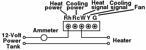
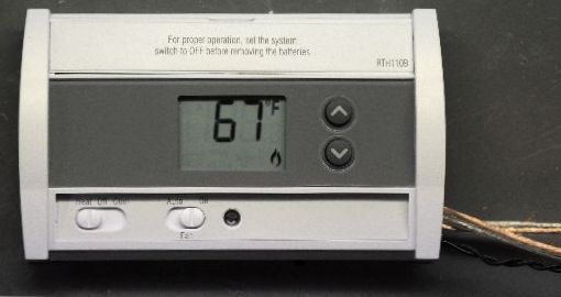
Electronic heater controllers are more efficient than rheostats. However, the distinction is not 100% clear-cut because the electronic circuitry in a switching device uses some power as well. For AC, you could use a variac. But usually, only DC power is available. Some commercial vendors use a pulse-width modulation controller. These can be easily made using a PWM generator chip such as the SG3525A (for circuit, see http://homepages.which.net/~paul.hills/Circuits/PwmGenerators/PwmGenerators.html ). These devices require filtering to reduce RF interference. But what we really need is not just any old controller, but a thermostat. Well, as luck would have it, you can buy a thermostat in most hardware stores for less than twenty bucks. The critical step here is to make sure you get a digital one, and not the mechanical type that uses a springy bimetallic mechanical sensor switch. These would work, but setting the temperature would be tricky. I used a Honeywell RTH110B non-programmable thermostat. The only modification that's necessary is to take it apart and move the thermistor to the inside of the shield.
If we were building a room heater, we would also need a relay. However, this thermostat can handle a load of 1 amp at 24 volts, which is more than we need. With a relay, it can even control an air conditioner, in case, at some point in the future, you decide to add an air conditioner to your telescope.
The main drawback of the RTH-110B thermostat is that its lowest setting is 41 degrees F. So in my area, it stays on most of the time. Another problem is that below 20°F (-6.6°C), the display just says "LO". This is your telescope's way of saying, "Go back inside and read a book or somethin'!" So it's advisable to have a separate thermometer to monitor the temperature.
There is also something called a "line voltage" thermostat like the Honeywell Linevolt PRO 7000 . Line voltage thermostats have built-in relays and are specifically designed for controlling electric heaters directly. It can handle up to 3840 watts, more than we will ever need!
Modifying the Thermostat
-
First, open the back cover of the thermostat and remove the RFID tag. This will prevent
the CIA's silent invisible black mind-control helicopters from tracking you. They
do not want you to see what's up there. Understandably so--there's some pretty junky-looking
stuff up there in orbit. (Or, maybe they just want you to think it's
junky-looking.)
-
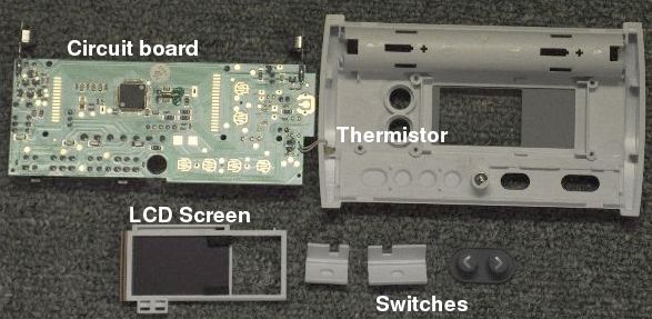
When you disassemble the Honeywell RTH-110B non-programmable electronic thermostat, a
number of pieces will fall out, including the LCD screen, circuit board, and the switch
buttons. Be careful not to lose the rubber connecting pad (known as a zebra strip) for
the LCD screen. If it gets dirty, you could lose a segment on the LCD. The thermistor
is the small yellow component that's glued into the front of the case. We need to get
this thermistor out and extend those two wires to about two feet.
- Gently pry the thermistor out of its compartment, cut the leads, and solder some 24 or 26 gauge wire to it. This is the hardest step, because nowadays insulation is so strong, it's tougher than the copper wire. It's a bit tricky to get the insulation off without nicking the wire. Cover the solder joints with heat shrink, and drill a hole in the side of the thermostat case for the wires. Pull the thermistor and its wire through the hole and seal it with hot-melt glue so the wires can't be pulled off the circuit board.
- Put heat-shrink over the solder joints on the thermistor end as well, taking care that the thermistor doesn't become hot. Then stuff the thermistor probe into a piece of plastic tubing to protect it further, turning it into a short temperature probe. Seal the ends and insert it into a hole in the side of the dew shield.
- Making sure the LCD rubber pad is immaculately clean, replace the circuit board in the thermostat and test all digits to make sure all the segments still work.
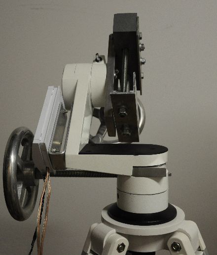
- Cover all remaining holes in the thermostat case with hot-melt glue to protect it against condensation, bugs, and other stuff. Mount it on a U-shaped bracket with the wires pointing down, so you can cover it up with a plastic bag to prevent snow and ice from getting inside it (see photo below). Alternatively, use a long sensor wire and keep the thermostat someplace warm. Over the temperature range we're using them, the resistance of thermistors changes by about 100-300Ω per degree C. So extending the cable shouldn't cause a problem as long as its resistance is low.
- Wire it up as shown below and test it to make sure it handles the current without exploding. Don't put more than 1 ampere through it unless you add a relay.
Attaching your dewshield to the telescope
"Is this yours, sir? What is this, some kind of a bomb?" --State trooper at your front door after finding your dewshield at the accident scene To keep the dewshield from falling off, rolling down the hill and out into the street, and being squashed flat by oncoming cars, you need to attach it to your telescope. I drilled four small holes in the protective light shield of the telescope about 1 cm from the end, tapped them with a 6-32 tap, and screwed the dewshield in place with ½-inch long stainless steel screws. Be sure to protect the corrector lens with a towel while you're drilling. If you don't like the idea of drilling holes in your scope, use Velcro or a large hose clamp. Then, of course, there's always the duct tape option.
Conclusion
That's it. The end result has a more professional appearance than a cardboard tube, and it's extremely light weight. The aluminum flashing has an attractive brushed metal appearance. It may not have the sophistication of professionally made dewshields like those from Kendrick, Astrozap, or Orion, but it works very well indeed.

Casa Blanca? ... more like a beige garage. Casa amarillento.